Earth (31) – troubleshooting
| Data sheet | |
| Please note | Diagnostics usually starts by checking the power supply. In this process, the opposite connection (earth) to the body, engine or battery is often not paid enough attention. However, this connection is just as significant |
Earth (31) – frequently neglected
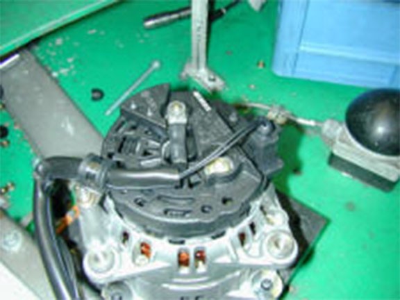
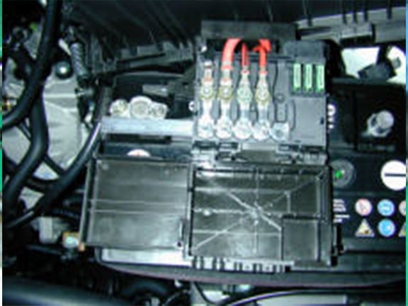
Particularly affected are the areas outside the vehicle interior, such as the alternator, starter, battery, ABS, ignition and injection system (engine electronics). However, the lighting system may also be affected.
Diagnostics usually starts by checking the power supply. In this process, the opposite connection (earth) to the body, engine or battery is often not paid enough attention. However, this connection is just as significant. Small amounts of dirt on terminals or connections can already have significant consequences. A formation of contact resistance can lead to voltage drops or leakage currents. These may lead to malfunctions or incorrect diagnoses.
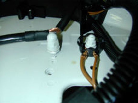
For this reason, earth connections are to be checked to ensure that they are secure and clean. Their metal should be clean, bright and free from dirt, paint and oxidation. Special contact sprays are available for protection. Also the cable ends secured to the connector and eyelets are to be checked. These may have come loose as a result of temperature fluctuations and vibrations. Water that has penetrated the cables may cause “internal corrosion” resulting in the associated malfunctions.
Measuring the resistance using a multimeter thus also forms part of the scope of testing as does measuring the voltage drop (if possible under load).
The following overview provides some reference points for cable resistance, cross sections, maximum continuous current and voltage drops:
| Cable cross-section | Max. resistance/m (20 °C) | Permissible continuous current |
| mm² | mO/m | A |
| 1 | 18.5 | 10 |
| 1.5 | 12.7 | 20 |
| 2.5 | 7.6 | 25 |
| 4 | 4.71 | 35 |
| 6 | 3.14 | 50 |
| 10 | 1.82 | 65 |
| 16 | 1.16 | 85 |
| 25 | 0.743 | 120 |
| 35 | 0.527 | 160 |
| 50 | 0.368 | 200 |
| 70 | 0.259 | 150 |
| 95 | 0.196 | 300 |
| 120 | 0.153 | 350 |
| Maximum permissible | Voltage drop inim | 12 Volt vehicle electrical system (an example) |
| Starter | Alternator | Lighting |
| Starter housing to body or engine block: | Alternator housing to body or to engine block: | voltage loss at positive cable and (in overall circuit): |
| 0.1 V | 0.1 V | |
| Negative battery terminal to body or to engine block: | Negative battery terminal to body or to engine block: | from light switch at terminal 30 to bulbs < 15 W: |
| 0.2 V | 0.2 V | 0.1 V (0.6 V) |
| Negative battery terminal to starter housing: | Negative battery terminal to alternator housing: | from light switch at terminal 30 to bulbs > 15 W: |
| 0.3 V | 0.3 V | 0.5 V (0.9 V) |
| Battery Plus to main power connection starter: | Battery plus to main power connection alternator | from light switch at terminal 30 to lamps: |
| 0.5 V | 0.4 V | 0.3 V (0.6 V) |
| Starter's main power connection under load (when starting): | ||
| 3.5V | ||
| Ignition switch to control current connection starter | ||
| 1.5 V |
* = Open-circuit voltage of the battery at least 12.4 volts for all test work
Reprinting, distribution, reproduction, exploitation in any form or disclosure of the contents of this document, even in part, is prohibited without our express, written approval; indication of the document source is also required. The schematic illustrations, pictures and descriptions are provided for explanatory purposes and are only intended as a visual supplement to the document text, so they cannot be used as the basis for installation or assembly work. All rights reserved.