Injection nozzle

Injection valves provide each cylinder with the required fuel and simultaneously atomise the fuel so that it can burn most effectively in the combustion chamber. Scroll through this page and find out how injection valves work and potential fault symptoms. You will also find useful tips for performing troubleshooting work on injection valves with the engine running and switched off.

Important safety note

The following technical information and practical tips have been compiled by HELLA in order to provide professional support to vehicle workshops in their day-to-day work. The information provided on this website is intended for suitably qualified personnel only.

1. Functional principle

How injection nozzles work

The purpose of injection valves is to precisely inject the fuel quantity calculated by the control unit in all engine operating states. To ensure the fuel is atomised effectively while minimising condensation losses, a certain engine-specific distance and injection angle need to be observed.

Injection valves are actuated electromagnetically. The control unit calculates and controls the electrical pulses for opening and closing the injection valves on the basis of the current sensor data regarding the engine operating state. Injection valves comprise a valve body, which houses a magnet winding and a guide for the nozzle needle, and a nozzle needle with magnet armature. When the control unit applies voltage to the magnet winding, the nozzle needle rises up from its valve seat and releases a precision bore hole. As soon as the voltage drops, a spring presses the nozzle needle back onto the valve seat and the bore hole is closed again.

The flow rate when the injection valve is open is precisely defined by the precision bore hole. In order to inject the fuel quantity calculated for the operating state, the control unit calculates the opening time for the injection valve in a comparison with the flow rate. This ensures that the precise fuel quantity is always injected. The design of the valve seat and the precision bore hole ensure that the fuel is optimally atomised.

2. Symptoms

Injection nozzle faulty

If an injection valve is faulty or not working properly, it can cause the following fault symptoms:

  • Problems starting
  • Increased fuel consumption
  • Loss of power
  • Fluctuating idle speed
  • Poor exhaust emission performance (e.g. emissions test readings)

Potential consequential damage:

  • Shorter engine service life
  • Damage to the catalytic converter and diesel particulate filter
3. Cause of failure

Causes of faulty injection nozzles

If the injection valve is faulty or has reduced functionality, the cause may be:

  • A blocked filter screen in the injection valve as a result of contaminated fuel
  • A poorly closing needle valve caused by tiny dirt particles from the inside, combustion residue from the outside, additive deposits
  • A clogged, closed outflow bore hole
  • A short circuit in the coil
  • A cable break to the control unit
4. Troubleshooting

Checking injection nozzles

Troubleshooting can be performed both when the engine is running and when it has been switched off.

Troubleshooting when the engine is running

1

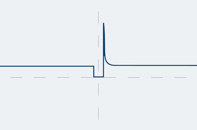
Compare the injected fuel quantity

Using a cylinder comparison measurement and simultaneous exhaust measurement, the injected fuel quantity can be compared based on the drop in speed and the HC and CO values for the individual cylinders. In the best case, the values will be identical for all cylinders. If there are major deviations between the values, it may be that not enough fuel is being injected (a large quantity of unburnt fuel = high HC and CO values, whereas little unburnt fuel = low HC and CO values). The cause may be a faulty injection valve.

2

Read off and compare the voltage and the pulse duration

The injection signal can be depicted using an oscilloscope. For this purpose, connect the measurement line to the signal line, and the other line to a suitable ground pin. With the engine running, it is possible to read off the voltage and the pulse duration (opening time) from the signal pattern. When opening the throttle valve, the pulse duration must increase during the acceleration phase, and with a constant engine speed (around 3000 RPM) it must fall back to, or just below, the idle value. The results of individual cylinders can be compared with each other, and this may provide an indication of potential faults, e.g. a poor voltage supply.

3

Measure the fuel pressure and check the intake and exhaust systems for leaks

Other important tests are measuring the fuel pressure, in order to identify other components that may be faulty (fuel pump, fuel filter, pressure regulator), and checking the intake and exhaust systems for leaks, to prevent false measurement results. If the sensor has a 2-pin connector, it is most likely to be an inductive sensor. In this case, the internal resistance, a potential short circuit to frame, and the signal can be determined.

To do this, remove the plug connection and check the internal resistance of the sensor. If the internal resistance value is 200 to 1,000 ohms (depending on the reference value), the sensor is OK. If the value is 0 ohms, there is a short circuit, and in the case of M Ohm there is a break. The test for a short circuit to frame is carried out using the ohmmeter from a connection pin to vehicle ground. The resistance value must tend toward infinity. The test using an oscilloscope must result in a sinus signal of sufficient strength. In the case of a Hall generator, only the signal voltage in the form of a square wave signal and the supply voltage are to be tested. This must result in a square wave signal depending on the engine speed. We should repeat at this point that the use of an ohmmeter can destroy the Hall generator.

Troubleshooting when the engine/ignition is switched off

1

Check the continuity of the cable connection

Check the continuity of the cable connection between the injection valves and the control unit (the circuit diagram for the pin assignment is required). In order to conduct this measurement, pull out the control unit connector and check the individual cables of the injection valve connectors to the control unit. Reference value: Approx. 0 ohms.

2

Check the cable connection for a short circuit to frame

Check for a short circuit to frame in the cable connection between the injection valves and the control unit. With the control unit connector pulled out, measure the cables from the injection valve connectors to the control unit against vehicle ground.

3

Check the continuity of the injection valve coils

Check the continuity of the injection valve coils. To do so, connect the ohmmeter between the two connection pins. Reference value: Approx. 15 ohms (note manufacturer specifications).

4

Check the injection valve coils for a short circuit to frame

Check the injection valve coils for a short circuit to frame. For this purpose, check the continuity of each individual connection pin against the valve housing. Reference value: >30 MOhm.

On a stationary test stand, it is possible to test the spray pattern of the injection nozzles when they are disassembled. Depending on the device manufacturer, it may also be possible to clean the injection valves.

How helpful is this article for you?

Not helpful at all
5
4
3
2
1
Very helpful
Success

Wrong Captcha

Wrong Captcha

Error

Something went wrong

Spare Parts Finder
Manualy Oe-No. Universal Parts
Top manufacturers
Other manufacturers
Vehicle series Back
Vehicle Back

Enter the OE number in the input field. You will usually find the OE number on the spare part itself or in the vehicle documents.

Spare Parts Finder
Simple vehicle identification Also determine spare parts with OE numbers Detailed product information Find wholesalers near you
dummy
Processing Selected Car

Choose category:
Back
dummy
Teilen Sie
Send via Copy link
URL copied to the clickboard !
Article NUmber
Number
Article Number Was Copied !
Search The Web Mounting Instructions
More Details
Name Value
Less Details

Your Dealer
Autoteile Krammer GmbH
dummy
Lechstraße 1-3
68199 Mannheim
Show Map

You might also be interested in

NOx-Sensor - Mercedes Benz
Basic Knowledge
NOx-Sensor - Mercedes Benz
If a fault is diagnosed in the NOx sensor when troubleshooting an exhaust gas purification system, this can present a small challenge for a workshop.
Reading time: 7 minute
Checking an alternator regulator
Basic Knowledge
Checking an alternator regulator
Function and design of the overrunning alternator pulley explained - including installation instructions for the overrunning alternator pulley on the alternator.
Reading time: 12 minute
Media pump
Basic Knowledge
Media pump - design, function and troubleshooting
Find out more about the function and system integration of the medium pump as well as testing and repair options.
Reading time: 7 minute
Generator freewheel function and installation instructions
Basic Knowledge
Function and assembly of the alternator freewheel clutch explained
Function and design of the overrunning alternator pulley explained - including installation instructions for the overrunning alternator pulley on the alternator.
Reading time: 2 minutes
Damage assessment starter motor
Basic Knowledge
Alternator damage assessment
How to diagnose damage to the alternator: from corrosion and short circuits to bearing damage.
Reading time: 1 minute
Damage assessment starter motor
Basic Knowledge
Starter damage assessment
Faulty starter motor? Discover typical causes such as overloading or misfiring and how to repair damage effectively.
Reading time: 1 minute
Check multifunction controller
Basic Knowledge
Check multi-function regulator
Find out how to check the multifunction regulator, measure the generator voltage and ensure that the regulator is functioning correctly.
Reading time: 4 minute
Testing alternators
Basic Knowledge
Checking the alternator
Detailed solutions for problems with the alternator - from testing to troubleshooting, everything for your vehicle workshop.
Reading time: 8 minute
Check the starter
Basic Knowledge
Checking the starter - Causes of failure, troubleshooting
Everything you need to know about typical starter motor faults and how to rectify them - with instructions for testing and repair.
Reading time: 9 minute
Service work on the loading system
Basic Knowledge
Service work on the charging system
Step-by-step instructions for servicing the charging system, including visual inspection and signal testing on the controller.
Reading time: 6 minute

Great! Just one more Step

Subscription successful

Head to your inbox and confirm your email address so that you don’t miss our updates!

Get ready for brand new technical videos, car repair advice, trainings, helpful diagnostic tips, marketing campaigns and much more... delivered straight to your inbox every two weeks!