Crankshaft sensor

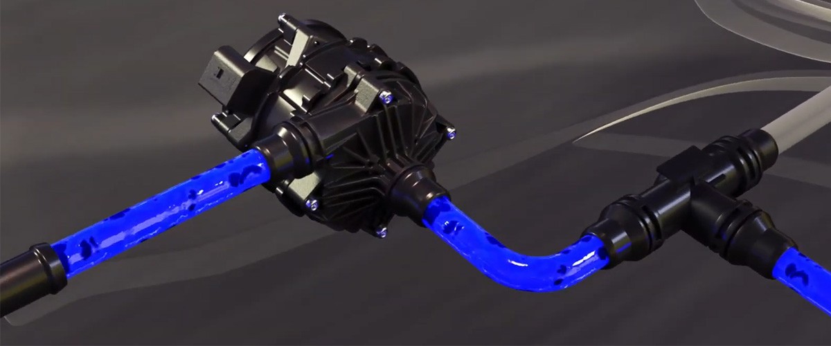
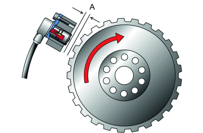
The crankshaft sensor is one of the key providers of information of the engine control. It detects the speed and position of the crankshaft and forwards this information to the engine control in the form of an electrical signal. On this page, you can find out how crankshaft sensors work, and what must be taken into account when checking them in order to prevent damage.

Important safety note

The following technical information and practical tips have been compiled by HELLA in order to provide professional support to vehicle workshops in their day-to-day work. The information provided on this website is intended for suitably qualified personnel only.

1. Functional principle

Crankshaft position sensor function

The function of crankshaft sensors is to measure the crankshaft's speed and position. They are most commonly installed near to the flywheel ring gear. There are two designs: Inductive sensors and Hall generators. Before the crankshaft sensor is tested, it is essential to know which type of transmitter is involved.

The rotary movement of the ring gear results in changes to the magnetic field. These generate varying voltage signals in the crankshaft sensor, which are transmitted to the control unit. The control unit uses the signals to calculate speed and position of the crankshaft in order to gain important basic data for injection and ignition timing.

2. Symptoms

Crankshaft sensor defective

A faulty crankshaft sensor can cause the following symptoms:

  • Engine stalls
  • Engine standstill
  • Problems starting
  • Error code is stored
3. Cause of failure

Causes of defective crankshaft sensors

Causes of failure can be:

  • Internal short circuits
  • Breaks in wiring
  • Wiring short circuit
  • Mechanical damage to the encoder wheel
  • Soiling caused by metal abrasion
4. Troubleshooting

Checking the crankshaft sensor

Troubleshooting:

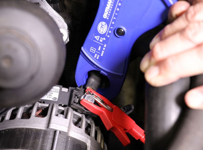
The following procedure is recommended for troubleshooting:

    1. Read out the fault memory
    1. Check the electrical connections of the sensor wiring, the connector, and the sensor for correct connection, breaks, and corrosion.
    1. Watch out for soiling and damage

Direct checks on the crankshaft sensor can be difficult if the exact design type of the sensor is not known. Before the checks, it must be clear whether the sensor is an inductive sensor or Hall generator. It is not always possible to distinguish between the two in terms of appearance. If there are three pins on the connector, no precise statements can be made about the respective type. The specific manufacturer specifications and the specifications in the spare-parts catalog provide further assistance here.

If the design type has not been definitively clarified, an ohmmeter must not be used for the tests. The voltage from the measuring device used for the resistance test could destroy a Hall generator!

If the sensor has a 2-pin connector, it is most likely an inductive sensor. In this case it is possible to determine the internal resistance, a potential short circuit to frame, and the signal. To do this, remove the plug connection and check the internal resistance of the sensor. If the internal resistance value is 200 to 1,000 ohms (depending on the reference value), the sensor is OK. If the value is 0 ohms, there is a short circuit, and in the case of M Ohm there is an interruption. The test for a short circuit to frame is carried out using the ohmmeter from a connection pin to vehicle ground. The resistance value must tend toward infinity. The test using an oscilloscope must result in a sinus signal of sufficient strength. In the case of a Hall generator, only the signal voltage in the form of a square wave signal and the supply voltage are to be tested. This must result in a square wave signal depending on the engine speed.

We should warn again at this point that the use of an ohmmeter can destroy the Hall generator.

Assembly instructions

Make sure that the distance to the encoder is correct and that the sensor is fitted correctly.

How helpful is this article for you?

Not helpful at all
5
4
3
2
1
Very helpful
Success

Wrong Captcha

Wrong Captcha

Error

Something went wrong

Spare Parts Finder
Manualy Oe-No. Universal Parts
Top manufacturers
Other manufacturers
Vehicle series Back
Vehicle Back

Enter the OE number in the input field. You will usually find the OE number on the spare part itself or in the vehicle documents.

Spare Parts Finder
Simple vehicle identification Also determine spare parts with OE numbers Detailed product information Find wholesalers near you
dummy
Processing Selected Car

Choose category:
Back
dummy
Teilen Sie
Send via Copy link
URL copied to the clickboard !
Article NUmber
Number
Article Number Was Copied !
Search The Web Mounting Instructions
More Details
Name Value
Less Details

Your Dealer
Autoteile Krammer GmbH
dummy
Lechstraße 1-3
68199 Mannheim
Show Map

You might also be interested in

NOx-Sensor - Mercedes Benz
Basic Knowledge
NOx-Sensor - Mercedes Benz
If a fault is diagnosed in the NOx sensor when troubleshooting an exhaust gas purification system, this can present a small challenge for a workshop.
Reading time: 7 minute
Checking an alternator regulator
Basic Knowledge
Checking an alternator regulator
Function and design of the overrunning alternator pulley explained - including installation instructions for the overrunning alternator pulley on the alternator.
Reading time: 12 minute
Media pump
Basic Knowledge
Media pump - design, function and troubleshooting
Find out more about the function and system integration of the medium pump as well as testing and repair options.
Reading time: 7 minute
Generator freewheel function and installation instructions
Basic Knowledge
Function and assembly of the alternator freewheel clutch explained
Function and design of the overrunning alternator pulley explained - including installation instructions for the overrunning alternator pulley on the alternator.
Reading time: 2 minutes
Damage assessment starter motor
Basic Knowledge
Alternator damage assessment
How to diagnose damage to the alternator: from corrosion and short circuits to bearing damage.
Reading time: 1 minute
Damage assessment starter motor
Basic Knowledge
Starter damage assessment
Faulty starter motor? Discover typical causes such as overloading or misfiring and how to repair damage effectively.
Reading time: 1 minute
Check multifunction controller
Basic Knowledge
Check multi-function regulator
Find out how to check the multifunction regulator, measure the generator voltage and ensure that the regulator is functioning correctly.
Reading time: 4 minute
Testing alternators
Basic Knowledge
Checking the alternator
Detailed solutions for problems with the alternator - from testing to troubleshooting, everything for your vehicle workshop.
Reading time: 8 minute
Check the starter
Basic Knowledge
Checking the starter - Causes of failure, troubleshooting
Everything you need to know about typical starter motor faults and how to rectify them - with instructions for testing and repair.
Reading time: 9 minute
Service work on the loading system
Basic Knowledge
Service work on the charging system
Step-by-step instructions for servicing the charging system, including visual inspection and signal testing on the controller.
Reading time: 6 minute

Great! Just one more Step

Subscription successful

Head to your inbox and confirm your email address so that you don’t miss our updates!

Get ready for brand new technical videos, car repair advice, trainings, helpful diagnostic tips, marketing campaigns and much more... delivered straight to your inbox every two weeks!