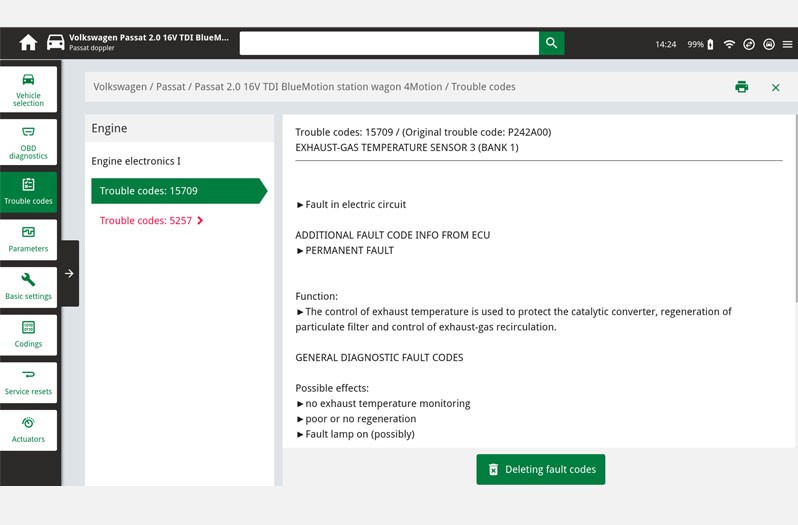
Checking the exhaust gas temperature sensor

In modern vehicle models, exhaust gas temperature sensors are installed at various points in the exhaust gas system in both diesel and petrol vehicles. The exhaust gas temperature sensor detects the temperature, for example, in front of the catalytic converter or diesel particulate filter and sends this as a voltage signal to the engine control unit. The engine control unit needs this information in order to control the air-fuel ratio or the particulate filter regeneration and thus effectively reduce emissions. In addition, high temperature sensors protect components in the area of ​​the hot exhaust gas flow from critical overheating.

Important safety note

The following technical information and practical tips have been compiled by HELLA in order to provide professional support to vehicle workshops in their day-to-day work. The information provided on this website is intended for suitably qualified personnel only.

1. Design and function

Exhaust gas temperature sensor

An electrical resistor is installed in the measuring tip of the exhaust gas temperature sensor, the value of which changes depending on the temperature. These resistors are called thermistors and are divided into two groups. Here a distinction is made between NTC thermistors and PTC thermistors, depending on their temperature behaviour ( Figure 1 ).

NTC - resistor with negative temperature coefficient (the resistance decreases with increasing temperature)

PTC - resistor with positive temperature coefficient (the resistance increases with increasing temperature)

The exhaust gas temperature sensor (EGTS) is usually connected directly to the engine control unit (ECU). Together with another resistor (RUP) in the control unit, the sensor forms a series connection through which an electrical voltage is divided. The signal is measured at the voltage divider and converted into temperature information by an algorithm ( Figure 2 ).

2. Effects

Exhaust gas temperature sensor - Symptoms

The following effects can occur in the event of an exhaust gas temperature sensor failure:

  • Warning lamp for glow plug system flashes
  • Warning lamp for particulate filter lights up
  • Engine control lamp is on
  • Increase in exhaust emissions (CO, NOx and HC)
  • Poor driving behaviour because of shortened regeneration intervals of the particulate filter 
  • Increased fuel consumption caused by longer particulate filter regeneration
  • Loss of performance caused by incorrect detection of the degree of saturation of the particulate filter
3. Causes of failure

Exhaust gas temperature sensors - defective

The following causes can be responsible for the failure of the exhaust gas temperature sensor:

  • Power supply faulty
  • External damage
  • Internal damage to the electrical wiring caused by strong vibrations in the exhaust gas system
  • Excessively high exhaust gas temperatures as a result of defects in the injection system or in the air-fuel mix
4. Troubleshooting

Checking the exhaust gas temperature sensor

System overview

The following information is illustrated using a VW Passat 2.0 16 V TDI from the year 2015 as an example. Depending on the vehicle features, up to four exhaust gas temperature sensors can be installed. Engine control monitors the temperature before the catalytic converter, turbocharger and also upstream and downstream of the diesel particulate filter.

In vehicles without a SCR (Selective Catalytic Reduction) catalytic converter, the exhaust gas temperature sensor behind the diesel particulate filter is not required. In the event of a defective exhaust gas temperature sensor or in the case of implausible output values, the system switches to emergency operation or alternatively uses a substitute value to protect the relevant components from overheating. An error entry is then recorded in the engine control unit and the warning lamp in the dashboard is activated.

Testing with the diagnostic unit

The function of the exhaust gas temperature sensor is monitored by the respective higher-level system control unit. Any errors that occur are stored in the error memory of the control unit and can be replaced by using a suitable diagnostic unit. Depending on the system, additional parameters can be displayed and used for troubleshooting.

1

Error code

In this function the error codes stored in the error memory can be read out and deleted. In addition, information on the error code can be called up.

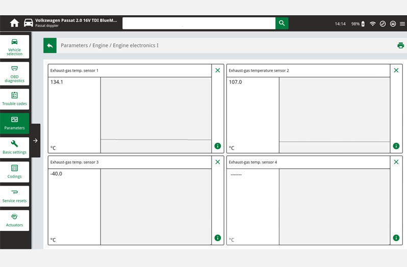
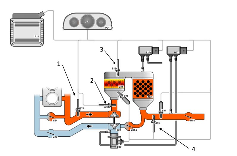
  • In our case study the error codes 15709 and 5257 are displayed, codes which indicate a fault in exhaust gas temperature sensor 3.

2

Parameters

In this function, the current measured values of the sensor in the control unit can be displayed and evaluated.

  • Illustration shows a vehicle with three exhaust gas temperature sensors
  • Sensor 3 shows a value of minus 40 degrees, which may be due to an interruption in the electrical wiring or to a defect in the sensor.

3

Circuit diagrams

System-specific circuit diagrams can be taken from vehicle information and used for troubleshooting purposes. Here the PIN assignment on the exhaust gas temperature sensor or the cable colours can be read off and used for further tests.

Maintenance and repair instructions!

  • As part of troubleshooting, a visual inspection of the components and peripherals in the engine compartment should first be carried out after the ECU diagnosis.
  • The sensor should be replaced if the connecting cable or sensor housing is damaged.
  • If the threads of the exhaust gas temperature sensors are coated, they must not be treated with an extra coating of hot thread paste.
  • Exhaust gas temperature sensors must be tightened to the specified tightening torque! We recommend a tightening torque of 40 - 45 Nm for HELLA exhaust gas temperature sensors.

Please also observe the respective maintenance and repair instructions provided by each individual vehicle manufacturer!

Important!

The various diagnostic options have been illustrated using the mega macs 77 diagnostic unit as an example. The respective test depth and variety of functions can be set out differently depending on the vehicle manufacturer and is dependent on the relevant system configuration of the control unit.

Schematic illustrations, pictures and descriptions serve to explain and illustrate the document text and cannot be used as a basis for vehicle-specific repairs.

How helpful is this article for you?

Not helpful at all
5
4
3
2
1
Very helpful
Success

Wrong Captcha

Wrong Captcha

Error

Something went wrong

Spare Parts Finder
Manualy Oe-No. Universal Parts
Top manufacturers
Other manufacturers
Vehicle series Back
Vehicle Back

Enter the OE number in the input field. You will usually find the OE number on the spare part itself or in the vehicle documents.

Spare Parts Finder
Simple vehicle identification Also determine spare parts with OE numbers Detailed product information Find wholesalers near you
dummy
Processing Selected Car

Choose category:
Back
dummy
Teilen Sie
Send via Copy link
URL copied to the clickboard !
Article NUmber
Number
Article Number Was Copied !
Search The Web Mounting Instructions
More Details
Name Value
Less Details

Your Dealer
Autoteile Krammer GmbH
dummy
Lechstraße 1-3
68199 Mannheim
Show Map

You might also be interested in

NOx-Sensor - Mercedes Benz
Basic Knowledge
NOx-Sensor - Mercedes Benz
If a fault is diagnosed in the NOx sensor when troubleshooting an exhaust gas purification system, this can present a small challenge for a workshop.
Reading time: 7 minute
Checking an alternator regulator
Basic Knowledge
Checking an alternator regulator
Function and design of the overrunning alternator pulley explained - including installation instructions for the overrunning alternator pulley on the alternator.
Reading time: 12 minute
Media pump
Basic Knowledge
Media pump - design, function and troubleshooting
Find out more about the function and system integration of the medium pump as well as testing and repair options.
Reading time: 7 minute
Generator freewheel function and installation instructions
Basic Knowledge
Function and assembly of the alternator freewheel clutch explained
Function and design of the overrunning alternator pulley explained - including installation instructions for the overrunning alternator pulley on the alternator.
Reading time: 2 minutes
Damage assessment starter motor
Basic Knowledge
Alternator damage assessment
How to diagnose damage to the alternator: from corrosion and short circuits to bearing damage.
Reading time: 1 minute
Damage assessment starter motor
Basic Knowledge
Starter damage assessment
Faulty starter motor? Discover typical causes such as overloading or misfiring and how to repair damage effectively.
Reading time: 1 minute
Check multifunction controller
Basic Knowledge
Check multi-function regulator
Find out how to check the multifunction regulator, measure the generator voltage and ensure that the regulator is functioning correctly.
Reading time: 4 minute
Testing alternators
Basic Knowledge
Checking the alternator
Detailed solutions for problems with the alternator - from testing to troubleshooting, everything for your vehicle workshop.
Reading time: 8 minute
Check the starter
Basic Knowledge
Checking the starter - Causes of failure, troubleshooting
Everything you need to know about typical starter motor faults and how to rectify them - with instructions for testing and repair.
Reading time: 9 minute
Service work on the loading system
Basic Knowledge
Service work on the charging system
Step-by-step instructions for servicing the charging system, including visual inspection and signal testing on the controller.
Reading time: 6 minute

Great! Just one more Step

Subscription successful

Head to your inbox and confirm your email address so that you don’t miss our updates!

Get ready for brand new technical videos, car repair advice, trainings, helpful diagnostic tips, marketing campaigns and much more... delivered straight to your inbox every two weeks!