Regulating an alternator: functions, diagnostics and tips for the workshop
Cutting-edge regulating of the alternator is a decisive factor when it comes to reliability and efficiency in motor vehicles. It ensures that the battery is always optimally charged and that the electrical consumers in the vehicle electrical system are supplied with the necessary energy. In view of all the complex vehicle electrical systems now present and also because of increasing electrification, precise alternator regulation is necessary in order to optimise performance, fuel consumption and emissions.
Important safety note
The following technical information and practical tips have been compiled by HELLA in order to provide professional support to vehicle workshops in their day-to-day work. The information provided on this website is intended for suitably qualified personnel only.
The alternator regulator ensures that the voltage generated by the alternator in the vehicle electrical system is kept at an optimum level. This means that the battery is properly charged in accordance with the battery type installed in the vehicle and it also ensures a stable power supply in the vehicle electrical system. The result is that overcharging of the battery and also damage to control units caused by overvoltage are both prevented.
The history of alternator regulation in motor vehicles goes back to the early days of the automotive industry when simple mechanical regulators were used for voltage stabilisation. Mechanical regulators are no longer used in series production, but are still available as spare parts. With the increase in electronic components in vehicles, mechanical regulators have been replaced by modern electronic regulators that enable more precise control.
Some advantages of electronic regulators:
Short switching times enable low control tolerance.
Electronic regulators are maintenance-free.
They can be used in various types of alternators because modern electronic regulators are designed for high switching currents.
Electronic regulators are insensitive to shocks, vibrations and climatic influences. They are therefore very reliable even under extreme conditions.
The compact design allows direct mounting to the alternator.
Electronic regulators can be divided into two types: hybrid technology and monolith technology.
Hybrid technology
An example illustration showing the circuit diagram of a regulator in hybrid technology. (1) Control unit , (2) Power output stage
Hybrid regulators combine digital and analogue components that are installed on a carrier. As a result of the large number of components, there are more connections than those found with monolithic regulators, a fact which can increase the susceptibility to errors. Hybrid regulators are generally larger and less compact than monolithic regulators and are often used in older or less compact alternators. Efficiency can be impaired by the large number of connections and by the different materials in use.
Monolith technology
An example illustration showing the circuit diagram of a regulator in monolith technology. (1) Control unit, (2) Power output stage
This is a further development of the hybrid regulator. Monolithic regulators combine all functions on a single chip, thus resulting in a more compact design. As a result of the reduced number of connections, they are less susceptible to faults and offer greater reliability than that provided by hybrid regulators. Monolithic regulators are generally smaller and more compact and are mostly used in modern, compact alternators. Efficiency is increased by the integration of all functions on one chip and by the reduced number of connections.
2. Variants
Variants of the alternator regulator
Depending on the installation space, various alternator regulators can be installed in the vehicle. In older vehicles or construction machinery with limited accessibility, the regulator is often installed separately, a situation which makes maintenance easier and which also prevents overheating.
The space available plays a decisive role in modern vehicles. Regulators that are mounted directly in or on the alternator housing are therefore often used in order to save space and maximise efficiency.
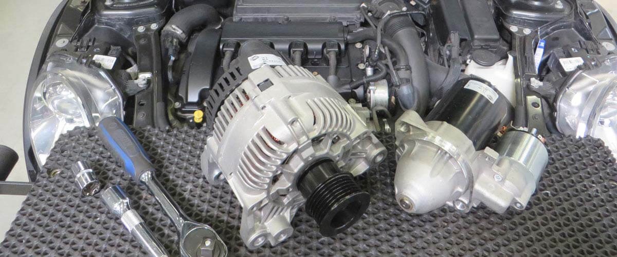
Regulator on the alternator (mounted on it)
Regulator outside the alternator (installed apart)
Regulator is located on the alternator (mounted on it): attached directly to the alternator. Replacement usually requires the alternator to be removed.
Regulator is located outside the alternator (installed apart): found in older vehicles and construction machinery. This facilitates maintenance.
Regulator is located in the alternator (integrated): installed in the alternator housing. Replacement often involves a great deal of work. In some cases it makes more economic sense to replace the alternator.
3. Interesting facts
Energy efficiency - Use of modern regulators in the car charging system
The alternator regulator plays a central role in the charging systems of modern cars. By using modern regulators, such as the
multifunction regulator (MFR)
, energy management in the vehicle electrical system can be controlled more efficiently and more precisely. The multifunction regulator contributes to improved vehicle efficiency and reliability thanks to its capabilities regarding battery monitoring, idle current cut-off, load control, fault diagnosis and engine management support.
A further development deals with regulators that have a LIN data bus interface for communication. Integration into the data bus systems enables even more precise charging control.
The LIN bus (Local Interconnect Network) is a serial communication system that was specially developed for the automotive industry. It enables cost-effective and reliable communication between various electronic control units and sensors in the vehicle.
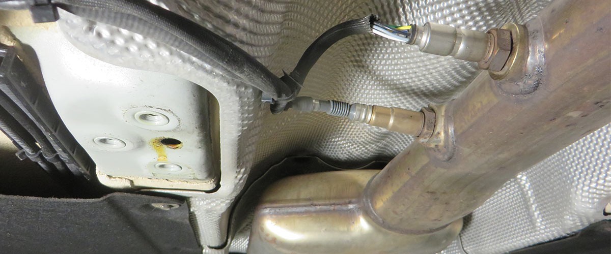
The regulator can communicate and exchange data with other control units and vehicle systems. With the help of various sensor values, such as the intelligent battery sensor (IBS), the higher-level control unit can optimise the charging control to suit the various operating states.
The intelligent battery sensor is attached directly to the negative pole terminal of the vehicle electrical system battery. It also uses the LIN bus for communication and continuously records information on the current status of the battery. The IBS measures the battery voltage, the output current, and the temperature of the battery. This data can be used to determine the current state of charge (SOC) and the state of health (SOH) of the battery. This ensures the best possible charging of the vehicle electrical system battery.
For example, the charging voltage can be adjusted to suit the ambient temperature if necessary. At low temperatures, it is increased in order to charge the battery optimally. At high temperatures, it is lowered to prevent overcharging of the vehicle electrical system battery.
In addition, the alternator can be switched off completely during acceleration phases so that a large proportion of the engine's energy is utilised for acceleration. This reduces fuel consumption and provides the driver with more engine power, for example when overtaking.
In overrun mode, the fuel supply is interrupted by the engine control unit, a procedure which is known as overrun cut-off. This means that no fuel is consumed. If the battery state of charge permits, the alternator output can be increased to a maximum during this phase so that the vehicle's kinetic energy is converted into electrical energy and the battery is charged without consuming additional fuel.
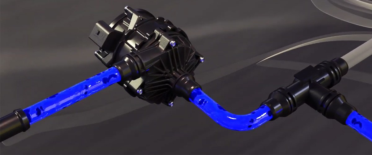
In this operating state, the increased alternator output causes a braking torque to act on the crankshaft via the belt drive. A freewheel pulley is installed on the alternator to ensure that the mechanical stress does not cause any damage to the belt drive during this phase. This
alternator freewheel
reduces the load on the components in the belt drive by decoupling the alternator.
The LIN connection of the alternator regulator also simplifies diagnostics and troubleshooting, too. Errors are recognised independently by the regulator and stored in the engine control unit. The stored error codes can be read out and analysed directly so that faults can be detected and rectified more quickly during everyday workshop operations.
4. Practical tips
Checking the alternator - tips for maintenance and diagnostics
Before starting the electrical test on the alternator, a few points on the surrounding components should be checked first.
The complete belt drive should be visually inspected. The following is a list of points to be observed:
Are cracks already visible in the ribs of the V-ribbed belt or are parts of the ribs coming away?
Are grinding or squeaking noises audible in the area of the tension and idler pulleys during operation or is rust visible?
Is there any damage on the surface of the belt pulleys or does the tension pulley swing back and forth a lot during operation?
If one of the above cases applies, the affected component must be checked more closely and replaced if necessary. The current state of charge of the vehicle electrical system battery should be checked. This can be determined by measuring the battery voltage at the terminals with a standard voltmeter. A good battery should show a voltage of 12.4 to 13.2 volts as an open-circuit voltage. If this is not the case, the battery must first be charged and then the measurement repeated. If the measured value after charging the battery is still not satisfactory, the battery should be checked with a battery tester and replaced if necessary .
All electrical connections on the alternator are to be checked for firm seating. The positive battery cable on the alternator must also be checked. Is it correctly secured and in good condition? Is there any damage to the insulation that could allow water to penetrate? If there are any anomalies, the voltage drop must be checked. The ground lines should also be checked for damage and corrosion. If there are any anomalies, then the voltage drop can also be checked here.
Important:
Please observe the relevant maintenance and repair instructions of each individual vehicle manufacturer for all tests on the starting and charging system!
5. Troubleshooting
Checking the alternator regulator - control unit diagnostics for alternator regulation: Control unit diagnostics
1
Reading the error memory
In this function, the error codes stored can be read out and deleted. The description of the faults includes general information on possible effects or causes, which is helpful for troubleshooting during the daily routine in the workshop.
Error memory query, error code description
2
Parameters
In this function, current measured values such as:
Engine speed
Alternator load signal
Current battery state of charge
Current battery voltage
can be queried.
This parameter query can be used during running to check whether the alternator is working properly.
Current measured values: parameter query
3
Measurement technology: LIN bus testing with the oscilloscope
By using a diagnostic device in combination with a measurement technology module, the oscilloscope can be used in the low-voltage measurement range to check the LIN bus directly on the alternator. If the LIN bus is not interrupted, a communication protocol is visible on the oscilloscope. If no protocol is visible, the cables and plug connections on the LIN bus should be checked.
In order to check the alternator voltage, the red terminal (+) was connected to the alternator terminal B+ and the black terminal (-) to the alternator ground.
Snapshot of the LIN signal and the alternator voltage, measured directly at the alternator
Checking the battery voltage and the LIN signal during operation
6. Fault patterns
Analysing harmonics - Insight into the alternator status
The exemplary illustration shows a typically good harmonic effect. Although the wavy line may vary slightly depending on the alternator or oscilloscope used, the uniformity of the harmonics indicates that the alternator's diodes are OK.
An example illustration shows an interruption of the negative diode
An example illustration shows an interruption of the positive diode.
An example illustration shows an interruption of the excitation diode.
Checking the alternator after installation is an important first step in troubleshooting. The alternator produces alternating voltage. Despite the rectification by the built-in diodes, a certain residual ripple, the so-called harmonic ripple, remains. By analysing this ripple with an oscilloscope, conclusions can be drawn about the condition of the alternator.
Direct voltage measurement at the battery positive terminal enables efficient checking of the alternator function and this does not involve much work. During the test, the alternator must be loaded by switching on consumers such as light functions, rear window heating and seat heating. The measurement is taken at an engine speed of around 2,500 rpm.
Some error patterns that can be recognised on the basis of the harmonics are shown below.
7. Symptoms
Diodes in the alternator defective? Symptoms and causes
Symptoms of defective diodes in the alternator can include an illuminated charging indicator lamp, fluctuating light intensity of the lamps, starting problems because of a discharged vehicle electrical system battery and also a discharged battery caused by quiescent currents.
One possible reason for defective diodes is increased resistance between the positive battery connection on the alternator and the positive terminal of the battery. This high resistance can be caused by an incorrectly fastened screw connection or corrosion on the electrical connections. This leads to an increased current flow through the diodes, which means they overheat and ultimately cause the alternator to fail.
A similar effect can occur if the battery is defective and the alternator charges the battery at maximum power because of this defect. This can cause the alternator to overheat, which can damage the diodes and also the windings and connections inside the alternator.
Swapping around the electrical connections of the alternator can also lead to a defect in the diodes. And disconnecting the battery while the engine is running or during a jump start can also lead to failure.
8. Interesting facts
Notes on changing the battery
The type of battery installed in the vehicle is to be observed. Depending on the manufacturer, so-called intelligent car charging systems often avoid fully charging the vehicle electrical system battery in order to be able, among other things, to store energy from recuperation (energy recovery). For this reason, the alternator charging voltage is often lower in these systems in order to enable better charging capacity of the battery. The vehicle electrical system battery must be replaced using a suitable diagnostic device. If the battery change is not registered, the new battery may never be fully charged.
The installation of a different type of battery should only be carried out in accordance with the manufacturer's specifications. For example, in charging systems such as the Smart Charge system with a silver-calcium battery, charging voltages of 14.8 V or sometimes even higher values can occur. These high charging voltages are not suitable for normal lead-acid batteries and can lead to damage or destruction of the battery. In the worst case, the battery can create the generation of gas, leading to an increased risk of explosion.
9. Installation instructions
Replacing the alternator regulator - Important installation instructions
Mounting aid on the new regulator: this safety pin must be removed after installation
Possible terminal designation of the various regulator manufacturers
As a rule of thumb, the following is to be observed when replacing an alternator regulator:
Switch off the ignition
Disconnect the battery's minus cable
Disconnect the connection cable from the alternator or regulator. If necessary, mark the cable connection with the terminal designation.
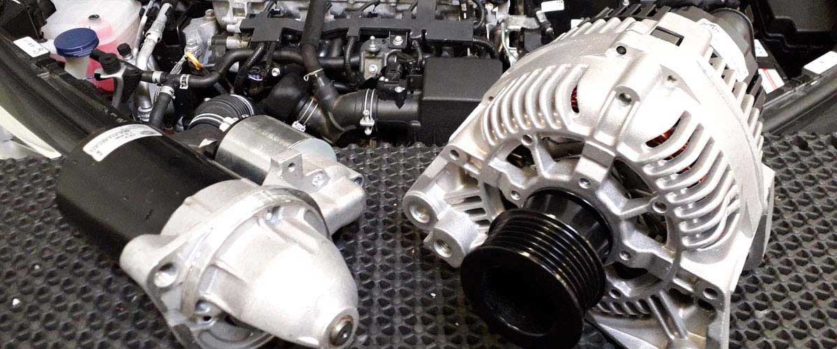
Remove the old regulator and compare it with the new regulator. Check the connector and terminal labelling. (see table)
Check the condition of the alternator. Check the slip rings and replace if necessary.
Install new regulator
Connect battery and check functioning of alternator
When installing, always ensure that the connection terminals and cables are securely connected. Avoid tilting the carbon brushes. On some types of regulator, the carbon brushes are fixed in place with a mounting aid to prevent any damage. This safety pin must be removed after installing the regulator.
Important:
Please always observe the maintenance and repair notes provided by the vehicle manufacturer when carrying out such work and checks!
The various diagnostic options were illustrated using the
mega macs X
in combination with the MT-HV measurement technology module as examples. The respective test depth and variety of functions can be set out differently depending on the vehicle manufacturer and these are dependent on the relevant system configuration of the control unit.
Schematic illustrations, pictures and descriptions serve to explain and illustrate the document text and cannot be used as a basis for vehicle-specific repairs.
How helpful is this article for you?
Not helpful at all
5
4
3
2
1
Very helpful
Success
Sign up for our free HELLA TECH WORLD newsletter to receive the latest technical videos, car repair advice, training course information, marketing campaign details and diagnostic tips.