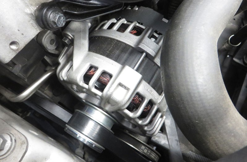
Check multi-function regulator

Important safety note

The following technical information and practical tips have been compiled by HELLA in order to provide professional support to vehicle workshops in their day-to-day work. The information provided on this website is intended for use by suitably qualified personnel only.

1. Basics

Alternator with multi-function regulator (MFR)

The ever increasing demand for electrical power requires particularly efficient and powerful alternators and regulators. These should have the option of consumer and battery management. For this reason, hybrid regulators are increasingly being replaced by monolithic regulators with new functions: these are called multi-function regulators

2. Function

Functions of a multi-function regulator

Multi-function regulators offer the following additional functions:

  • Battery monitoring (sensing)
  • Utilisation monitoring
  • Fault diagnostics
  • Engine management support
  • Load response

A multi-function regulator's functions in detail

In battery monitoring, the charging voltage of the battery is monitored via "S” connection, which is usually connected directly to the positive battery pole. The direct connection to the battery has the advantage that the existing voltage difference between alternator "+" and battery "+" is taken into account. This means that the charging voltage can be adapted even better to the battery voltage.

With the load control, it is possible to control the power of the alternator during the starting process and when the engine is running. This means that, during the starting process and directly after the engine start, the alternator does not output any current. This prevents the starting process from being prolonged by the full power (braking torque) of the alternator. If there are increased demands during the journey, leading to an increase in torque at the alternator, these are not passed on directly to the engine. The load response slowly increases the power output of the alternator.

The multi-function regulator also controls the pre-excitation current. After switching on the ignition, the regulator output stage starts to cycle in the set clock ratio. The alternator receives information that the ignition is switched on via connection terminal "L". The alternator control lamp remains on while the pre-excitation is active. The evaluation of the phase voltage identifies that the alternator is rotating. If pre-excitation is missing, e.g. due to a faulty plug contact, the emergency mode ensures excitation of the alternator. The idle current cut-off reduces the current consumption of the regulator as much as possible when the ignition is switched off.

If the battery monitoring line to battery "+" is disconnected, an "emergency regulation" takes place via the "B+" connection on the alternator. To protect the regulator against overheating, the temperature is measured on the IC. If the temperature rises too high, the controller voltage is reduced

Multi-function regulator connections

“L” = The “L” connection has several functions. The "L" connection is used to display the alternator function and any faults that have occurred. The control lamp is actuated via the lamp output stage. Consumers can also be connected via a relay output stage. The consumers should only be switched on when the alternator has reached its full output in fault-free operation. For this, the "L” connection provides an output current via the relay output stage. To detect faults, all signals are constantly evaluated by the regulator and any faults that occur are detected. A fault is indicated by the control lamp turning on via the lamp output stage. The lamp and relay output stages are protected against overload and short circuits. Here, the lamp output stage is active during alternator pre-excitation or when a fault is detected. The relay output stage for connecting the consumers is active during fault-free alternator operation when the lamp output stage is inactive.

"S" = The "S" connection is connected directly to battery "+" to measure the battery voltage as an actual value.

"DFM" = The "DFM” connection (DF monitor) facilitates recording the alternator’s present utilisation status. This makes it possible to react to certain situations, such as raising the idle speed or switching off consumers that are not required. The signal curve of "DF" can be picked up at the "DFM" connection.

"W" At the "W" connection, it is possible to pick up the voltage signal of an alternator phase.

3. Cause of failure

General effects and causes of a multi-function regulator failure

A multi-function regulator failure can have the following effects:

  • The alternator control lamp lights up
  • Discharged battery

Causes of failure can be traced back to various causes:

  • Interrupted output stage
  • Overvoltage in the vehicle electrical system
  • Charging cable interrupted
  • Battery monitoring cable interrupted
  • Fault in/on the alternator (broken drive belt, short circuit in the excitation circuit, etc.)

These errors are detected by the multi-function regulator depending on the regulator type

4. Troubleshooting

Check multi-function regulator:

1

Visual inspection

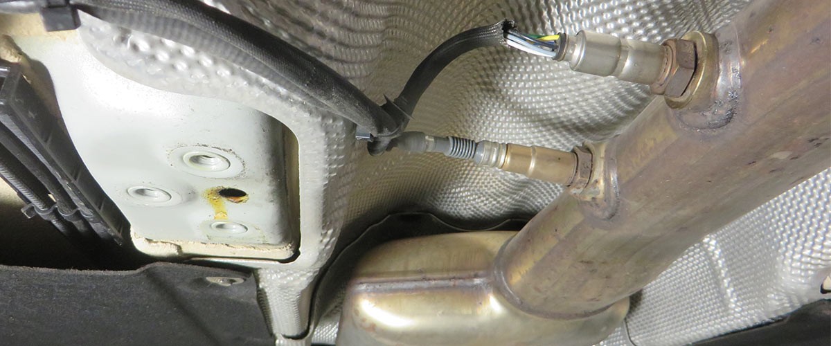
  • Check all cable connections and plug contacts for correct routing and contacting.
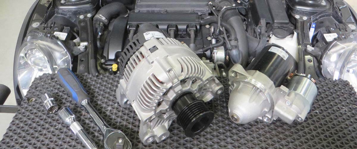
    Check alternator drive belt for correct tension and any cracks

2

Measure the alternator voltage/alternator

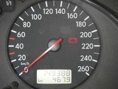
Measure the alternator voltage/alternator current at the battery (observe manufacturer's specifications, differences between manufacturers). Carry out measurements at idle speed and increased engine speed, without and with consumers connected.

3

Checking the signal at controller connection „DFM“

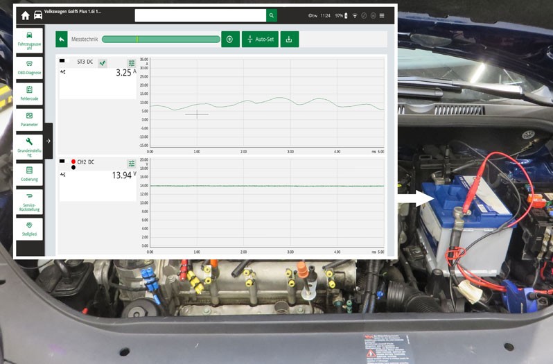
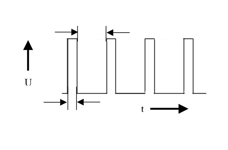
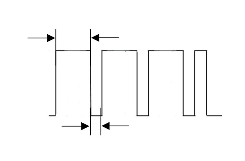
Record the signal at the DFM connection with the oscilloscope. The signal shown reflects the duty cycle of the excitation current. Depending on the load condition of the alternator, the duty cycle must change.

Link to tip

Here you will find tips and remedies for specific symptoms and causes for the failure of a defective alternator . In addition, we show you on this page how to check the charging system , such as carrying out a visual inspection before diagnosis, testing the batteries, performing the alternator test and testing with the diagnostic device. You can find more product information about starters and alternators from Hella here

How helpful is this article for you?

Not helpful at all
5
4
3
2
1
Very helpful
Success

Wrong Captcha

Wrong Captcha

Error

Something went wrong

Spare Parts Finder
Manualy Oe-No. Universal Parts
Top manufacturers
Other manufacturers
Vehicle series Back
Vehicle Back

Enter the OE number in the input field. You will usually find the OE number on the spare part itself or in the vehicle documents.

Spare Parts Finder
Simple vehicle identification Also determine spare parts with OE numbers Detailed product information Find wholesalers near you
dummy
Processing Selected Car

Choose category:
Back
dummy
Teilen Sie
Send via Copy link
URL copied to the clickboard !
Article NUmber
Number
Article Number Was Copied !
Search The Web Mounting Instructions
More Details
Name Value
Less Details

Your Dealer
Autoteile Krammer GmbH
dummy
Lechstraße 1-3
68199 Mannheim
Show Map

You might also be interested in

NOx-Sensor - Mercedes Benz
Basic Knowledge
NOx-Sensor - Mercedes Benz
If a fault is diagnosed in the NOx sensor when troubleshooting an exhaust gas purification system, this can present a small challenge for a workshop.
Reading time: 7 minute
Checking an alternator regulator
Basic Knowledge
Checking an alternator regulator
Function and design of the overrunning alternator pulley explained - including installation instructions for the overrunning alternator pulley on the alternator.
Reading time: 12 minute
Media pump
Basic Knowledge
Media pump - design, function and troubleshooting
Find out more about the function and system integration of the medium pump as well as testing and repair options.
Reading time: 7 minute
Generator freewheel function and installation instructions
Basic Knowledge
Function and assembly of the alternator freewheel clutch explained
Function and design of the overrunning alternator pulley explained - including installation instructions for the overrunning alternator pulley on the alternator.
Reading time: 2 minutes
Damage assessment starter motor
Basic Knowledge
Alternator damage assessment
How to diagnose damage to the alternator: from corrosion and short circuits to bearing damage.
Reading time: 1 minute
Damage assessment starter motor
Basic Knowledge
Starter damage assessment
Faulty starter motor? Discover typical causes such as overloading or misfiring and how to repair damage effectively.
Reading time: 1 minute
Testing alternators
Basic Knowledge
Checking the alternator
Detailed solutions for problems with the alternator - from testing to troubleshooting, everything for your vehicle workshop.
Reading time: 8 minute
Check the starter
Basic Knowledge
Checking the starter - Causes of failure, troubleshooting
Everything you need to know about typical starter motor faults and how to rectify them - with instructions for testing and repair.
Reading time: 9 minute
Service work on the loading system
Basic Knowledge
Service work on the charging system
Step-by-step instructions for servicing the charging system, including visual inspection and signal testing on the controller.
Reading time: 6 minute
Check electronic boost pressure control turbocharger actuator
Basic Knowledge
Electronic boost pressure control- turbocharger actuator testing
Learn how the electronic boost pressure control works and how the turbocharger actuator is tested on a Mercedes-Benz.
Reading time: 8 minute

Great! Just one more Step

Subscription successful

Head to your inbox and confirm your email address so that you don’t miss our updates!

Get ready for brand new technical videos, car repair advice, trainings, helpful diagnostic tips, marketing campaigns and much more... delivered straight to your inbox every two weeks!