Secondary air injection system

The secondary air system reduces harmful exhaust constituents during the cold start phase. On this page, you can find out precisely how this works. Here you can also read how malfunctions in the secondary air system become noticeable and how they can be precisely located during troubleshooting.

Important safety note

The following technical information and practical tips have been compiled by HELLA in order to provide professional support to vehicle workshops in their day-to-day work. The information provided on this website is intended for suitably qualified personnel only.

1. Basics

Why is a secondary air system used?

This system further lowers the HC and CO values during the cold start phase when the catalytic converter is not yet active.

A conversion rate of over 90 percent is achieved using a 3-way catalytic converter in stoichiometrically operated gasoline engines. On average, up to 80 percent of the emissions of a driving cycle are emitted during a cold start. However, because the catalytic converter only works effectively from temperatures of approx. 300°C – 350°C, the emissions must be lowered during the cold start phase using different measures. This is the task of the secondary air system.

If there is sufficient residual oxygen in the exhaust system and the temperature is high enough, the HC and CO react in a secondary reaction to form CO2 and H2O.

To ensure there is enough oxygen for the reaction during the cold start phase, when the mixture is very rich, air is added to the exhaust flow. For vehicles with a three-way catalytic converter and a lambda control , the secondary air system is switched off after approx. 100 seconds. The operating temperature of the catalytic converter is quickly reached through the heat generated in the secondary reaction.

The secondary air can be supplied actively or passively. In the passive system, fluctuations in pressure in the exhaust system are utilised. Additional air is drawn in via a timed valve due to the vacuum created through the flow speed in the exhaust pipe. In an active system, the secondary air is blown in by a pump. This system allows better control.

2. Structure

Structure of the active secondary air system

1 Air filter
2 Secondary air pump
3 Engine control unit
4 Control relay
5 Change-over valve
6 Combination valve
---------- currentless

3. Function

Function of the active secondary air system

The active secondary air system usually consists of an electric pump (see figure), the control relay, a pneumatic control valve, and a combination valve. The system is controlled by the engine control unit.

While the system is working, the electric pump is switched on by the engine control unit via the control relay. The pneumatic control valve is actuated at the same time. The valve opens and the vacuum from the intake pipe operates the combination valve.

The vacuum causes the combination valve to open and the additional air conveyed by the pump is pumped into the exhaust pipe behind the exhaust valves. As soon as the lambda control becomes active, the secondary air system is deactivated. The engine control unit deactivates the electric pump and the pneumatic control valve. The combination valve is also closed, preventing hot exhaust emissions from reaching the electric pump and damaging it.

4. Symptoms

Fault symptoms in the event of failure

Increased emission values during the cold start and warm-up phases can be caused by a lack of post-combustion. The catalytic converter only reaches its operating temperature at a later point. Secondary air systems which are monitored by the engine control unit's self-diagnosis function, cause the engine indicator lamp to illuminate in the event of faults.

5. Cause of failure

Causes of a failure

A faulty pump is generally the most frequent cause of the system failing. Ingress of moisture can cause damage which results in seizure of the pump. Faulty ground and voltage supply can also cause the pump to fail. Blocked or leaking lines can also cause the failure or malfunction of the control or combination valve, resulting in the failure of the secondary air system.

6. Troubleshooting

Troubleshooting and diagnostics on secondary air systems

As for all other troubleshooting and diagnostic work, begin with visual checks, and additionally an acoustic check. For the acoustic check, the electric pump is audible when the engine is cold and at idle. The sound of the pump stopping can also clearly be heard after the engine has been turned off. For the visual check, all components should be checked for damage. The cables and hose fittings should be checked particularly closely. These parts should be correctly attached to the components and not show any signs of chafing. They must also not be kinked or blocked due to excessively tight radii. The fuses must also be present and checked for damage. If during these tests no fault can be determined, a suitable diagnostic unit can be used for further diagnostics. The basic prerequisite is that the system has been provided with diagnostic capabilities by the vehicle manufacturer.

1

Reading stored faults

Any stored faults can be read out from the fault memory and rectified.

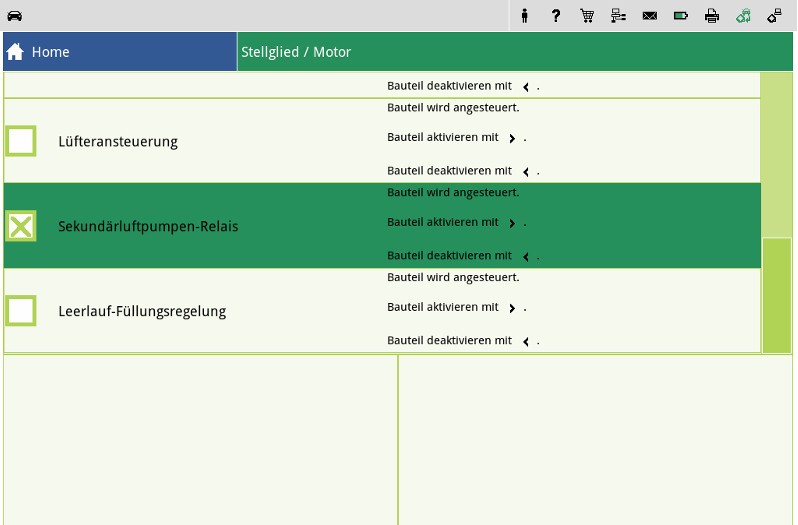
If no faults are stored in the fault memory, the electric pump can be switched on using the actuator test. During this test, the function of the control relay is also tested at the same time.

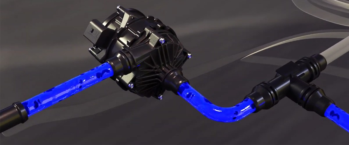
The triggering of the control valve can also be checked with the actuator test. The function of the control valve can also be tested without a diagnostic unit. For this, remove the vacuum line which leads to the combination valve. Start the cold engine.

2

Checking the vacuum at the control valve fitting

At the control valve fitting, it should be possible to detect a vacuum (a vacuum pump can also be connected) as soon as the secondary air pump begins to operate

3

Checking the triggering of the control valve

If no vacuum can be detected, check the triggering of the control valve using a multimeter. If this is OK, a faulty control valve can be presumed to be the cause.

4

Checking the function of the combination valve

The function of the combination valve can be checked using a vacuum pump. For this, remove the vacuum line at the combination valve and connect the vacuum pump to the valve.

5

Checking the hose fitting

Now loosen the hose fitting from the secondary air pump to the combination valve at the pump.

Blow air into the line with a slight pressure (do not use compressed air). The combination valve must be closed.

Apply a vacuum to the combination valve and blow air into the hose fitting again. The combination valve must now be opened. If the combination valve does not open, or if it is permanently open, the valve is faulty.

Note

During all diagnostic and testing procedures, information from the vehicle manufacturer should always be adhered to if possible. From manufacturer to manufacturer, there may be vehicle-specific information and testing methods which may have to be taken into consideration.

How helpful is this article for you?

Not helpful at all
5
4
3
2
1
Very helpful
Success

Wrong Captcha

Wrong Captcha

Error

Something went wrong

Spare Parts Finder
Manualy Oe-No. Universal Parts
Top manufacturers
Other manufacturers
Vehicle series Back
Vehicle Back

Enter the OE number in the input field. You will usually find the OE number on the spare part itself or in the vehicle documents.

Spare Parts Finder
Simple vehicle identification Also determine spare parts with OE numbers Detailed product information Find wholesalers near you
dummy
Processing Selected Car

Choose category:
Back
dummy
Teilen Sie
Send via Copy link
URL copied to the clickboard !
Article NUmber
Number
Article Number Was Copied !
Search The Web Mounting Instructions
More Details
Name Value
Less Details

Your Dealer
Autoteile Krammer GmbH
dummy
Lechstraße 1-3
68199 Mannheim
Show Map

You might also be interested in

NOx-Sensor - Mercedes Benz
Basic Knowledge
NOx-Sensor - Mercedes Benz
If a fault is diagnosed in the NOx sensor when troubleshooting an exhaust gas purification system, this can present a small challenge for a workshop.
Reading time: 7 minute
Checking an alternator regulator
Basic Knowledge
Checking an alternator regulator
Function and design of the overrunning alternator pulley explained - including installation instructions for the overrunning alternator pulley on the alternator.
Reading time: 12 minute
Media pump
Basic Knowledge
Media pump - design, function and troubleshooting
Find out more about the function and system integration of the medium pump as well as testing and repair options.
Reading time: 7 minute
Generator freewheel function and installation instructions
Basic Knowledge
Function and assembly of the alternator freewheel clutch explained
Function and design of the overrunning alternator pulley explained - including installation instructions for the overrunning alternator pulley on the alternator.
Reading time: 2 minutes
Damage assessment starter motor
Basic Knowledge
Alternator damage assessment
How to diagnose damage to the alternator: from corrosion and short circuits to bearing damage.
Reading time: 1 minute
Damage assessment starter motor
Basic Knowledge
Starter damage assessment
Faulty starter motor? Discover typical causes such as overloading or misfiring and how to repair damage effectively.
Reading time: 1 minute
Check multifunction controller
Basic Knowledge
Check multi-function regulator
Find out how to check the multifunction regulator, measure the generator voltage and ensure that the regulator is functioning correctly.
Reading time: 4 minute
Testing alternators
Basic Knowledge
Checking the alternator
Detailed solutions for problems with the alternator - from testing to troubleshooting, everything for your vehicle workshop.
Reading time: 8 minute
Check the starter
Basic Knowledge
Checking the starter - Causes of failure, troubleshooting
Everything you need to know about typical starter motor faults and how to rectify them - with instructions for testing and repair.
Reading time: 9 minute
Service work on the loading system
Basic Knowledge
Service work on the charging system
Step-by-step instructions for servicing the charging system, including visual inspection and signal testing on the controller.
Reading time: 6 minute

Great! Just one more Step

Subscription successful

Head to your inbox and confirm your email address so that you don’t miss our updates!

Get ready for brand new technical videos, car repair advice, trainings, helpful diagnostic tips, marketing campaigns and much more... delivered straight to your inbox every two weeks!