Depending on the field of application and on the operating conditions, the horn mounted onboard, also known as a klaxon, can have too weak a sound. In such cases it is useful to install a more powerful horn in order to be able to produce an adequate warning sound in the event of a dangerous situation. How to implement this modification and which points have to be considered in the process can be found on this website using Audi TT/RS and a Grand Cherokee jeep as examples.
Important safety note
The following technical information and practical tips have been compiled by HELLA in order to provide professional support to vehicle workshops in their day-to-day work. The information provided on this website is intended for suitably qualified personnel only.
The following retrofitting will now be shown using the example of an Audi TT/RS and a Grand Cherokee jeep. The instructions can also be used in conjunction with other vehicle models. Diagrams, pictures and descriptions serve only for the purposes of explanation and representation of these instructions and therefore cannot be used as a basis for the repair/conversion work.
Before starting the retrofit, the following points should be observed and, wherever necessary, carefully checked:
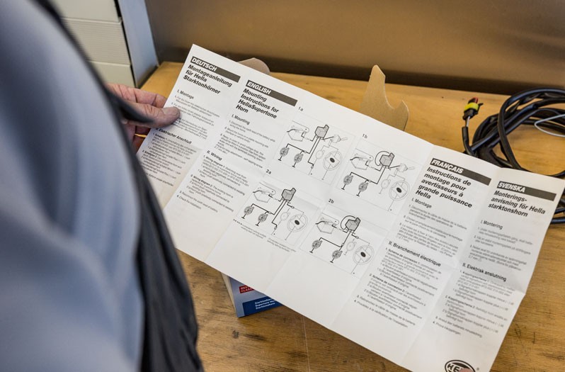
Take time to thoroughly read the mounting instructions enclosed with the product
Using the technical data available, calculate the power consumption of the super-tone horns
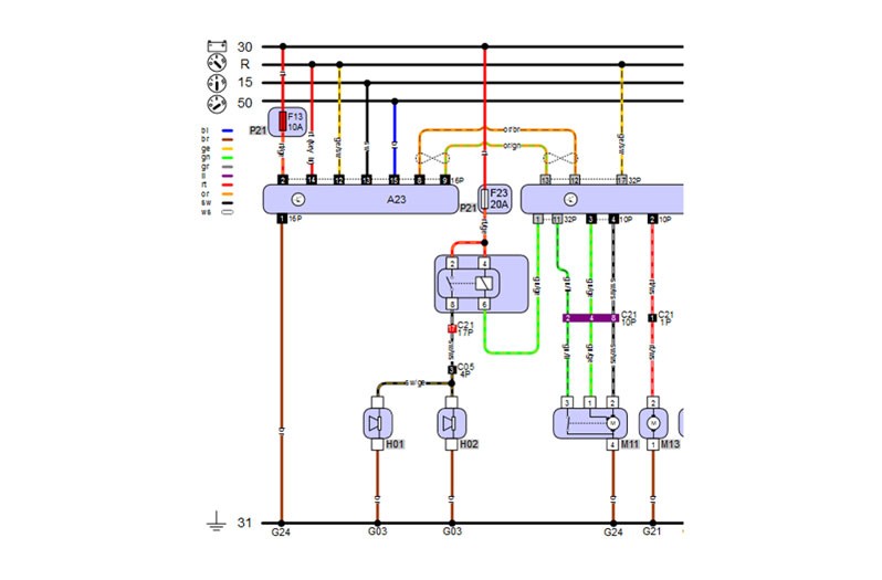
Then armed with this information, inspect the onboard wiring and safety features of the originally installed horns to ascertain their usefulness
The power consumption of the new super-tone horn is indicated with 66 watts, an amount which in a 12 volt vehicle wiring system corresponds, purely mathematically, to a current consumption with 11.0 amperes for both horns. In the vehicle which we are taking as an example, wiring with adequate wire cross-section, power relays and a 20A fuse have been already mounted in the factory. Therefore, in the case of a permanent load, there is the guarantee of sufficient power reserves throughout the entire circuit. Changing the electrical wiring in this case is not necessary
Important
If the onboard wiring or safety features are not adequate, then it is imperative to change these in order that they comply with the new installation situation.
2. Instructions
Car horn installation using the example of an Audi TT/RS
Preparatory work
The power supply of the acoustic signaling device is to be cut off throughout the entire setting up of the electrical connection.
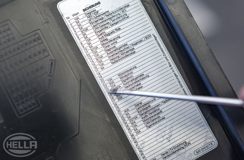
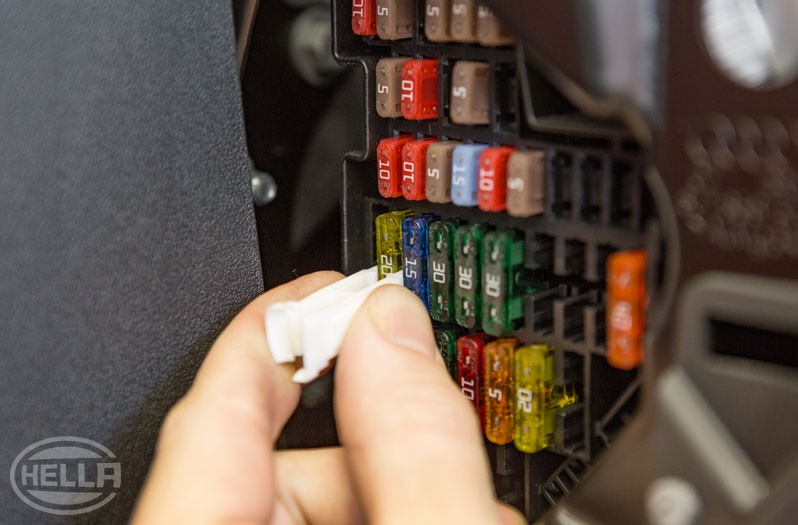
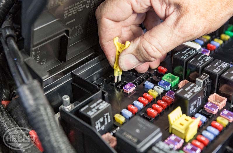
Remove fuse for the horn circuit from the fuse box
Disconnect the ground cable of the battery
Important: as a result of this disconnecting, several release codes (radio, navigation etc.) are cancelled and have to be re-entered
Important!
Switch off ignition and remove key from the vehicle.
1
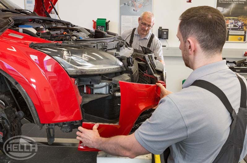
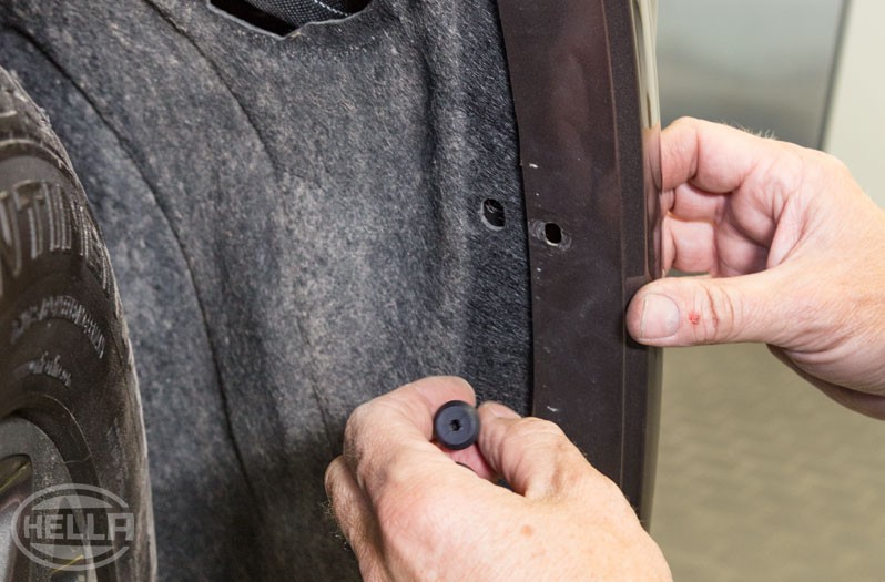
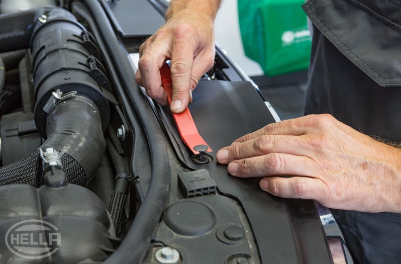
Removing front bumper cover
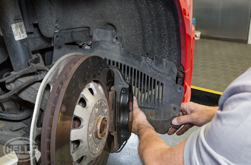
Unscrew screws of the wheel housing liner at the front, left and right
Remove the lower covering and push back the wheel housing liner
If necessary, disconnect the washer fluid pipes of the windscreen washer system and close them off
Unscrew the fastening screws of the bumper cover on the top, bottom and inside
Carefully remove the bumper cover
2
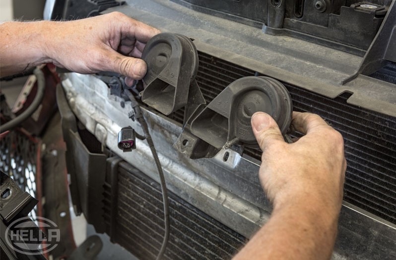
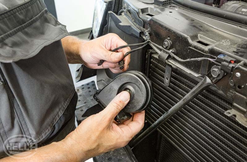
Dismounting originally installed horns with holders
Disconnect the electrical plug connections on the horns
Dismount the vertical reinforcement strut (holder/lock latch)
Dismount the holder with the horns
Remove the horns from the holder
3
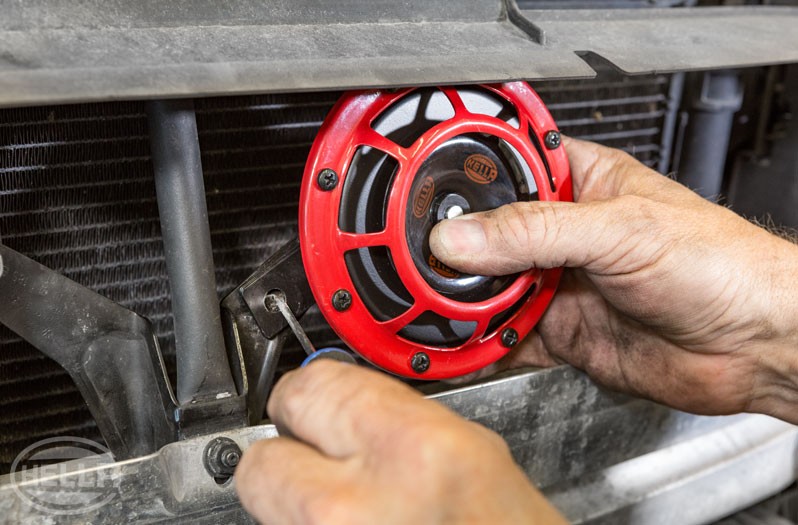
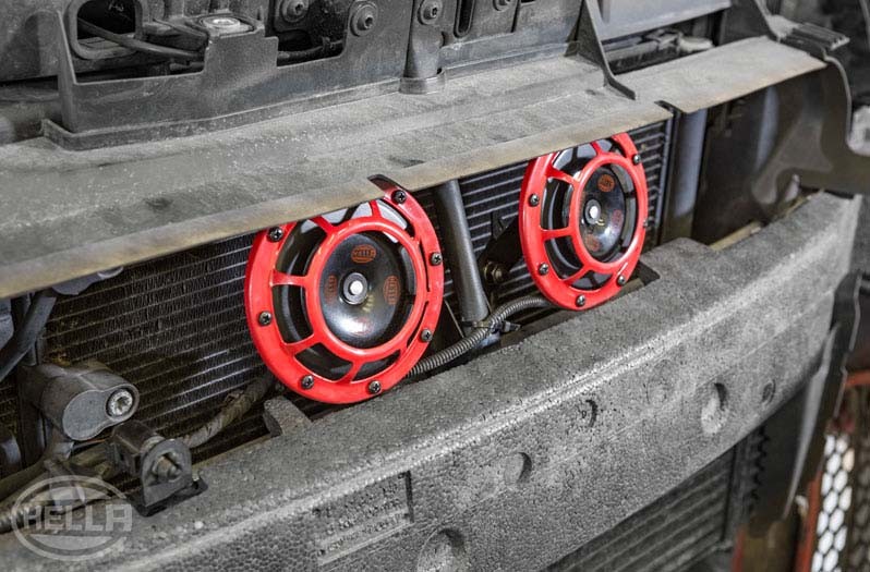
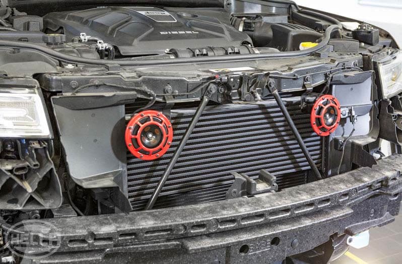
Mounting the super-tone horns
Remount the holder in order to determine the mounting position of the new horns
Mark the mounting position on the holder. Remove the mounting holder and drill in the required position
Then mount the holder and the reinforcement strut again and secure the horns on this bracket with the appropriate screws
Important!
Because of the size of the new super-tone horns, it is necessary to check that the best mounting position has been selected. The body of the housing must be given sufficient room on either side in order to oscillate and it should not touch any adjacent body parts.
4
Preparing electrical connections for the new super-tone horns
Undo the black, slotted corrugated pipe from the wiring harness
Disconnect the old connector on the wiring harness
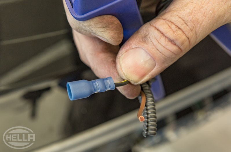
Strip the two wire ends of the cable and securely fasten two flat receptacles with a suitable crimping pliers
Place the two cables into the corrugated pipe again
If the installation positioning so demands, the cables can also be sheathed in heat-shrinkable plastic tubing
5
Connecting the super-tone horns
Connect the electrical connection to the super-tone horns, then plug in the wiring harness to the cable routing and secure.
6
Insert fuse and run a functional test
If the function test is successful, the bumper cover can then be mounted together with all its assembly parts, thus making the vehicle once again complete and ready for service.
Important!
The body of the housing including the retaining plate determines the tone of the horn. Any change occurring to the retaining plate (holder) of the super-tone horn can bring about a negative alteration to the acoustic pattern.
3. Instructions
Car horn installation using the example of a Grand Cherokee
Retrofitting on this vehicle is comparable as regards the basic structures involved. It is only the vehicle-specific mounting which has to be duly observed.
Vehicle-specific steps in the process
Remove fuse for the horn circuit from the fuse box
1
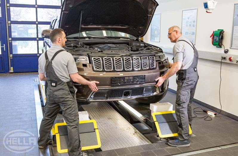
Removing front bumper cover
Remove underride protection and wheel housing covers
Release fastening elements of the bumper cover, top and bottom
Remove the bumper cover at the front
2
Dismounting originally installed horns with holders
Disconnect the electrical plug connections on the horns
Remove the horns from the holder
3
Mounting the super-tone horns
Define the mounting position of the new horns on the holder
Then fix the super-tone horns on it with the appropriate type of screws
4
Connect the electrical connection to the super-tone horns, then plug in the wiring harness to the cable routing and secure
With this vehicle, the holder and the electrical connection could be taken over without the need for any adjustments.
5
Functional test
Insert fuse and run a functional test
6
Reposition and mount the bumper cover again
Finally mount the bumper cover again with all its assembly parts
Important!
Extract from the General Regulations pursuant to the ECE ruling R28 on "Audible Warning Devices/ Signals" of the United Nations for Europe: "The device for audible signals has to produce a uniform and constant sound; its acoustic spectrum is not to noticeably change while in operation."
During all retrofitting and conversion work, it is imperative to observe the product-specific mounting and repair instructions of each individual vehicle manufacturer at all times!
Diagrams, pictures and descriptions serve only for the purposes of explanation and representation of the instructions and therefore cannot be used as a basis for installation/assembly work. All rights reserved.
How helpful is this article for you?
Not helpful at all
5
4
3
2
1
Very helpful
Success
Sign up for our free HELLA TECH WORLD newsletter to receive the latest technical videos, car repair advice, training course information, marketing campaign details and diagnostic tips.