Accelerator pedal sensor

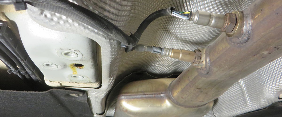
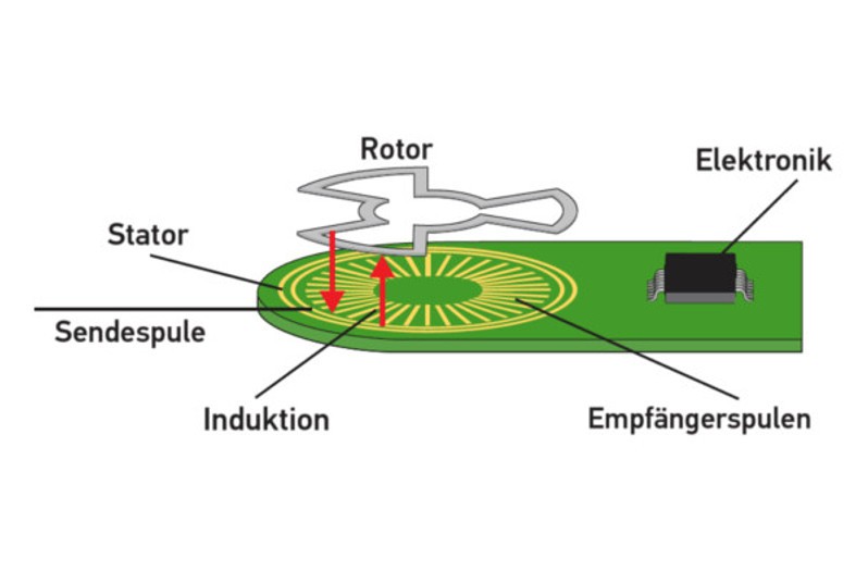
The accelerator pedal sensor transmits the position of the accelerator pedal to the engine control unit. Based on this information, the load requested by the driver can be implemented immediately. On this page we will explain the principle according to which modern pedal travel transmitters operate, and which symptoms indicate a fault in this sensor. You will also find out how accelerator pedal sensors are checked in the workshop.

Important safety note

The following technical information and practical tips have been compiled by HELLA in order to provide professional support to vehicle workshops in their day-to-day work. The information provided on this website is intended for suitably qualified personnel only.

1. Functional principle

How the accelerator pedal sensor works

Modern vehicles are being equipped with an ever-increasing number of electronic components. Among other things, this is due to legal regulations, e.g. those governing a reduction in emissions and fuel consumption. Electronic components are also increasingly being used to increase active and passive safety as well as driving comfort. One of the most important components is the accelerator pedal sensor.

When it comes to automotive applications, a non-contact sensor based on an inductive principle is increasingly being used. This sensor comprises a stator (which includes an excitation coil, receiver coils, and an electronic evaluation unit) and a rotor (formed of one or more closed conductive loops with a certain geometry).

The application of alternating voltage to the transmission coil produces a magnetic field which induces voltages in the receiver coils. A current is also induced in the rotor conductive loops which, in turn, influences the magnetic field of the receiver coils. Voltage amplitudes are produced depending on the position of the rotor relative to the receiver coils in the stator. These are processed in an electronic evaluation unit and then transmitted to the control unit in the form of direct-current voltage. This evaluates the signal and forwards on the relevant pulse, e.g. to the throttle valve actuator. The characteristics of the voltage signal depend on how the accelerator pedal has been pressed.

2. Symptoms

Symptoms of a faulty accelerator pedal sensor

If the accelerator pedal sensor fails, the following fault symptoms may occur:

  • Increased engine idling speed
  • Vehicle does not respond if the accelerator pedal is pressed
  • Vehicle switches to "limp-home mode"
  • Engine warning light in the cockpit illuminates
3. Cause of failure

Accelerator pedal sensor faulty

A failure could have a number of different causes:

  • Damaged cables or connections on the accelerator pedal sensor
  • Missing voltage and ground supply
  • Faulty electronic evaluation unit in the sensor
4. Troubleshooting

Checking the accelerator pedal sensor

The following test steps should be considered during troubleshooting:

  • Read out fault code
  • Visual inspection of the accelerator pedal sensor to check for mechanical damage
  • Visual inspection of the relevant electrical connections and cables to ensure they are properly fitted and for any damage
  • Check of the sensor using an oscilloscope and multimeter

Using the example of a MB A-Class (150) 1.7, the following test steps, technical data, and figures are listed to explain the troubleshooting work.

Control unit pinSignalTest conditionsReference value
C5 blue-yellowAcceleration off0 V
C5Acceleration off4,5 – 5,5 V
C8 violet-yellowAcceleration on0 V
C blue-greyAcceleration on,
accelerator pedal released
0,15 V
C9Acceleration on,
accelerator pedal pressed
2,3 V
C10 violet-greenAcceleration on,
accelerator pedal released
0,23 V
C10Acceleration on,
accelerator pedal pressed
4,66 V
C23 brown-whiteAcceleration on0 V

→ output signal ← input signal ⊥ control unit ground

SIGNAL RECORDING FROM PIN C5

This measurement checks the voltage supply to the sensor. Ignition on/off.

SIGNAL RECORDING FROM PIN C9

Ignition on, press pedal, then release pedal. The signal rises and falls depending on the speed at which the pedal is pressed and released

SIGNAL RECORDING FROM PIN C10

Ignition on, press pedal, then release pedal. The signal rises and falls depending on the speed at which the pedal is pressed and released.

RECOMMENDATION!

The measurements should be performed by two people. The work involved in capturing the signals on the sensor, carrying out various test cycles, and performing diagnostics work on the oscilloscope is difficult for a single person to handle, and it will take them much longer to complete this work.

Accelerator Pedal Training

In this video, we will show you the technologies of the accelerator pedals, how they work and discuss the faults. In addition, we will show the diagnosis of the element? using mega macs and tell you what to look for.

How helpful is this article for you?

Not helpful at all
5
4
3
2
1
Very helpful
Success

Wrong Captcha

Wrong Captcha

Error

Something went wrong

Spare Parts Finder Teaser
Manualy Oe-No. Universal Parts
Top manufacturers
Other manufacturers
Vehicle series Back
Vehicle Back

Enter the OE number in the input field. You will usually find the OE number on the spare part itself or in the vehicle documents.

Spare Parts Finder Teaser
Simple vehicle identification with License Plate Also determine spare parts with OE numbers Detailed product information Find wholesalers near you
dummy
Processing Selected Car

Choose category:
Back
dummy
Teilen Sie
Send via Copy link
URL copied to the clickboard !
Article NUmber
Number
Article Number Was Copied !
Search The Web Mounting Instructions
More Details
Name Value
Less Details

Your Dealer
Autoteile Krammer GmbH
dummy
Lechstraße 1-3
68199 Mannheim
Show Map

You might also be interested in

Basic Knowledge
Reading time: 1 minute
Basic Knowledge
Checking the exhaust gas temperature sensor
Step-by-step instructions for testing the exhaust gas temperature sensor - shown on the VW Passat 2.0 TDI.
Reading time: 3 minutes
Injection nozzle/injection valve
Basic Knowledge
Injection nozzle/injection valve – Function & checks
Find out how to diagnose a defective fuel injector and replace it in the workshop.
Reading time: 6 minutes
TPS sensor
Basic Knowledge
TPS sensor – function & troubleshooting
Learn how to check a throttle potentiometer for defects and recognize the most common symptoms.
Reading time: 2 minutes
Throttle valve switch
Basic Knowledge
Throttle valve switch – function & troubleshooting
Everything you need to know to diagnose and repair the throttle valve switch - helpful workshop tips.
Reading time: 2 minutes
Camshaft position sensor
Basic Knowledge
Camshaft position sensor - function & troubleshooting
Learn all about the function and testing of the camshaft sensor and possible symptoms of a defect.
Reading time: 2 minutes
Air-mass sensor
Basic Knowledge
Air-mass sensor - Function & troubleshooting
Learn how to check a mass air flow sensor, detect defective sensors and replace them professionally.
Reading time: 2 minutes
Car knock sensor
Basic Knowledge
Car knock sensor - function & troubleshooting
Find out how to check the knock sensor for malfunctions and rectify possible fault symptoms.
Reading time: 2 minutes
ABS sensor
Basic Knowledge
Check and change ABS and wheel speed sensors
Instructions for diagnosing and replacing the ABS sensor - all the steps for a professional repair.
Reading time: 10 minutes
ABS sensor
Basic Knowledge
Transmission range sensor circuit – troubleshooting
Everything you need to know about diagnosing transmission sensors - from troubleshooting to repairs in your garage.
Reading time: 2 minutes

Great! Just one more Step

Subscription successful

Head to your inbox and confirm your email address so that you don’t miss our updates!

Get ready for brand new technical videos, car repair advice, trainings, helpful diagnostic tips, marketing campaigns and much more... delivered straight to your inbox every two weeks!