Signal lights in cars

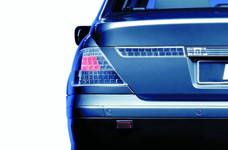
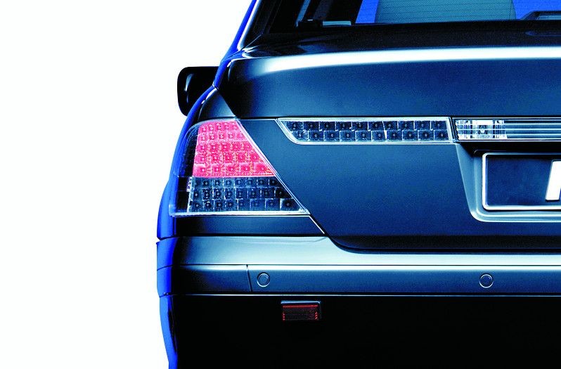
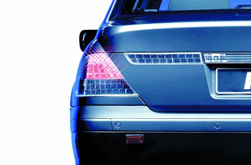
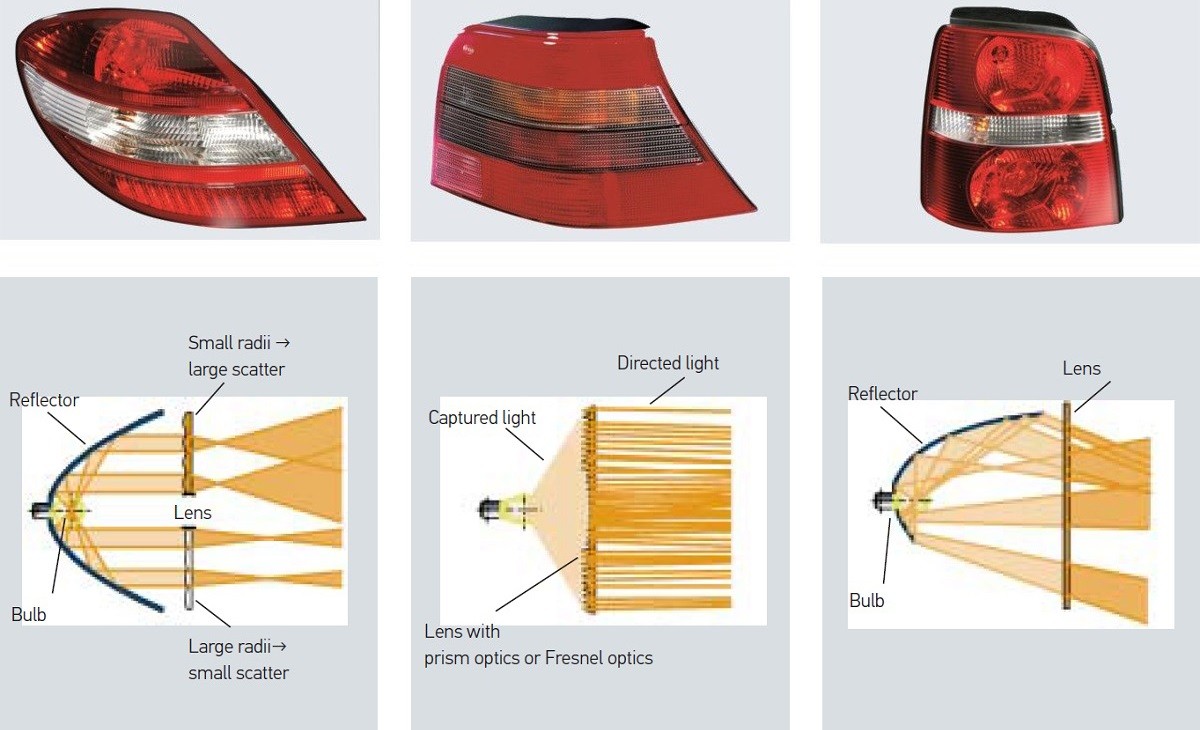
Signal lights have an important safety function. They demonstrate deceleration and a change in direction of the vehicle, and make the vehicle more visible to other road users when it is dark or during poor visibility. On this page, you can find out how signal lights are structured, and what technology is behind new signal systems. Here you can also find the most common causes of failure for signal lights, tips for troubleshooting, and information regarding important regulations.

Important safety note

The following technical information and practical tips have been compiled by HELLA in order to provide professional support to vehicle workshops in their day-to-day work. The information provided on this website is intended for suitably qualified personnel only.

1. Structure

Car indicator signal lights

Exterior lights – whether attached at the front, side or rear of the vehicle – provide information for other road users through their signals and are thus responsible for safety on the roads to a substantial extent.

A conventional passenger car signal light basically consists of three assemblies: The bulb holder, the housing, and the cover lens.

  • The bulb holder positions one or more light sources correctly in relation to the optical system of the light.
  • The housing contains the reflectors which are usually molded.
  • The cover lens is responsible for light distribution through additional patterned structures.

In order to meet the photometric requirements, the light from the light sources has to be collected and directed, deflected, and distributed. Several optical component parts are used for this purpose.

Signal lights: Optical systems with bulbs
Optical systems with bulbs
2. Function

Asignis® – Adaptives Signal-system

All the functions in a rear light only work on one brightness level, no matter whether they are switched on during the day, at night, or on a bright foggy morning. The only current possibility of adapting the lights to adverse weather conditions is the rear fog light. This is often used incorrectly, however, and leads to irritation. There is no additional information conveyed about whether the brakes are only being applied lightly or slammed on, for example.

Thanks to ASIGNIS®, the individual signal lights in a rear combination lamp (brakes, direction indicator etc.) can be adapted to the current situation. Depending on weather and visibility conditions the light intensity of the signals (e.g. brighter during the day and darker at night or with the braking signal) can be varied.

The requirement for differing braking signals can either be met by means of a larger signal area, an increase in brightness, or the addition of an increased flashing frequency. The stop light is activated in three stages dependent on deceleration: The greater the deceleration, the more LEDs light up. In the case of a hard stop, one part-array of the red stop light flashes as an additional warning function.

3. Practical tips

Tips for dealing with signal lights

In many vehicles, the light sources are controlled via pulse width modulation (PWM). This has several advantages for the vehicle lighting. For one thing, the same bulbs can be used for different functions, and the service life of the bulbs is increased.

The rear lamps of the Golf V also use PWM. PWM allows the use of a 21 W bulb both for the stop light and for the tail light. The pulse width is modulated in such a way that the 21 W bulb has almost the same luminous flux as a 5 W bulb. If the brake is now actuated, the turn-on time is so long, that 13.5 V is present at the stop light, and the 21 W bulb provides the full luminous flux (see illustration). Once the brake is released again, the voltage returns to 5.74 V.

When replacing bulbs in signal lights, the information and specifications of the manufacturer must always be adhered to. If an incorrect bulb is used, there is the danger that the required luminous intensity will not be reached.

4. Symptoms

Faulty signal lights

A faulty signal light can be detected from the following symptoms:

  • No signal is emitted for individual functions e.g. stop light. This leads to an increased safety risk, particularly during night-time driving
  • The indicator lamp on the dashboard lights up (failure monitor, if present)
  • Two lighting functions light up e.g. direction indicator and tail light
5. Troubleshooting

Checking signal lights

If a signal light fails, there are always several possible causes. The following points should be noted when troubleshooting:

  • Check the light sources and replace if necessary
  • Check the bulb holder for corrosion and contact interruption
  • Check the voltage supply including fuses
  • Check the plug-type connection for corrosion and mechanical damage
  • In vehicles with PWM, check the signals with an oscilloscope/diagnostic tester.
6. Good to know

Signal light regulations

Due to the scope of the statutory regulations, only the most important are explained here. The following regulations contain all the relevant information about signal lights, their properties, and uses:

76/759/EEC, ECE-R6, StVZO § 54
Direction indicators front, rear, and side

76/758/EEC, ECE-R7, StVZO §§ 51 and 53
Marker lights and tail lights front and rear

77/540/EEC, ECE-R77, StVZO § 51
Parking lights front and rear

ECE R87
Daytime running lights

77/539/EEC, ECE-R23, StVZO § 52
Reversing lights

76/758/EEC, ECE-R7, StVZO § 53
Stop lights

77/538/EEC, ECE-R38, StVZO § 53d
Rear fog lights

76/760/EEC, ECE-R4, StVZO § 60
License plate lamps

ECE R3
Reflex reflectors

Direction indicators front, rear, and side
Number at the frontTwo
Number at the rearTwo or four
Number at the side
(optional)
One per side
ColourAmber
Height positionBetween 350 mm and 1500 mm permissible
Width position
Side positionInstallation height between 350 mm and 1500 mm and max. 1800 mm from the front edge of the vehicle
Electrical circuitAn electronic warning flasher unit is made up of a pulse generator which switches the lights on via a relay. In addition, it also has a control circuit which is dependent on current and changes the flashing frequency in the event of light failure. The frequency of the flashing signals is between 60 and 120 per minute. All the direction indicators on the same side of the vehicle have to work synchronously.
Switch-on controlGreen indicator lamp
MiscellaneousDepending on the requirements, there are different functional controls for monitoring the indicator system (single-circuit, dual-circuit control).

Marker lights (passenger vehicles) front
NumberTwo or four
ColoursWhite, or amber when main headlamps are amber
MountingThe arrangement is the same as for the front direction indicators.
MiscellaneousVehicles and trailers over 1600 mm wide require marker lights (to the front).

Tail lights
NumberTwo or four
ColourRed
Height positionBetween 350 mm and 1500 mm permissible
Width positionMax. 400 mm from the outermost edge of the body. At least 600 mm apart
Electrical circuitNo particular specifications
MiscellaneousIn the event of dual function (stop and tail light), the luminous intensity ratio of the individual functions must be at least 5 to 1.

Rear fog lights
NumberOne or two
ColourRed
Height positionBetween 250 mm and 1000 mm permissible
Width positionThe distance to the stop light must be at least 100 mm.
Electrical circuitRear fog lights may only work when low beam, high beam, or fog lamps are switched on. They must be able to be switched off independently of the fog lamps.
Switch-on controlAmber, vehicles approved before 1981 also green
MiscellaneousThe visible illuminated area must not be more than 140 cm2. The light may only be switched on when visibility is less than 50 m.

License plate lamps
NumberDepending on requirements one or two lamps
ColourWhite
MountingNo particular specifications
Electrical circuitNo particular specifications
Switch-on controlAmber, vehicles approved before 1981 also green
MiscellaneousThe rear license plate must be illuminated in such a way that it can be read at a distance of 25 m. The minimum luminance of the complete surface area must be at least 2.5 cd/m2.

Reversing lights
NumberOne or two
ColourWhite
Height position250 to 1200 mm permitted
Width positionNo particular specifications
Electrical circuitThe circuit only works with the ignition switched on and the reverse gear engaged.

Parking lights
NumberDepending on requirements two at the front and two at the rear or one at each side
ColourWhite
Height positionBetween 350 mm and 1500 mm permissible
Width positionMax. 400 mm from the outermost edge of the body. At least 600 mm apart
Electrical circuitThe parking lights must be able to work without other lamps being switched on.
Switch-on controlAmber, vehicles approved before 1981 also green
MiscellaneousThe parking light function is usually taken over by the tail lights.

Side marker lights
NumberDepending on the length of the vehicle
ColourAmber
Height positionBetween 250 mm and 1500 mm permissible
Width positionMax. 3000 mm from the front edge of the vehicle and max. 1000 mm from the rear edge of the vehicle
Electrical circuitNo particular specifications

Daytime running lights
NumberTwo at the front
ColourWhite
Height positionBetween 250 mm and 1500 mm permissible
Width positionMax. 400 mm from the outermost edge of the body. At least 600 mm apart
Electrical circuitThe daytime running lights must switch off automatically if the low-beam headlamps are switched on.

Installation regulations side view

Signal light regulations: Installation regulations side view
Side marker lights (SML) / Side marker reflex reflectors (SMR) 1 SML/SMR: Max. 1000 mm (from rear vehicle edge) 2 All: Max. 3000 mm 3 Direction indicator: Max. 1800 mm SML/SMR: Max. 3000 mm (from front vehicle edge) 4 SMR: Max. 900 mm, SML: 1500 mm 5 SML/SMR: Min. 250 mm 6 SMR/SML: Min. 250 mm, direction indicator: 350 mm 7 SMR: Max. 900 mm, SML/direction indicator: 1500 mm

Installation regulations rear view

Signal light regulations: Installation regulations rear view
Side marker lights (SML) / Side marker reflex reflectors (SMR) 1 Valid for direction indicator/stop light/tail light/reflex reflector: Max. 600 mm 2 Valid for direction indicator/tail light/reflex reflector 3 Centre high-mounted stop lamp: Min. 850 mm 4 Rear combination lamp: Min. 350 mm 5 Rear combination lamp: Max. 1500 mm 6 Centre high-mounted stop lamp: Max. 150 mm below rear combination lamp or 3

Type approval numbers on signal lights

National and international design and operating regulations apply for the manufacture and testing of vehicle lighting equipment. Special approval marks exist for signal lights and can be found on the light.

One example
The following can be found on a light RS1 IAF 02 E1 Æ 31483:

  • R stands for tail light,
  • S1 for stop light,
  • IA for reflex reflector,
  • F for rear fog light and 02 means that the regulation has been revised twice since publication.

These features are integrated in the rear combination lamp:

  • The E1 marking means that the light has been approved in Germany.
  • The arrow shows which way the light can be installed and therefore always points to the outer edge of the vehicle. If there is no arrow on the light it can be installed at the right or left rear side.
  • The five-digit number at the end is the type approval number.

Help in decoding the combinations of numbers and letters on signal lights

A Marker light
AR Reversing light
F Rear fog light
IA Reflex reflectors
R Tail light
S1 Stop light
1 Front direction indicator (different technical design)
1a Front direction indicator (different technical design)
1b Front direction indicator (different technical design)
2a Rear direction indicator
5 Additional side direction indicator (for vehicles up to 6 m in length)
6 Additional side direction indicator (for vehicles longer than 6 m)
SM1 Side marker light (for all vehicles)
SM2 Side marker light (for vehicles up to 6 m in length)

The permissible luminous intensity values vary depending on the function. Changes in movement (braking = 60 cd) have a stronger lighting signal than those for position and orientation (tail light = 4 cd).

S Tail light
B Stop light
ZB Additional stop light
BL Direction indicator light
ZR Tail light
NES Rear fog light
PO Position light

How helpful is this article for you?

Not helpful at all
5
4
3
2
1
Very helpful
Success

Wrong Captcha

Wrong Captcha

Error

Something went wrong

Spare Parts Finder Teaser
Manualy Oe-No. Universal Parts
Top manufacturers
Other manufacturers
Vehicle series Back
Vehicle Back

Enter the OE number in the input field. You will usually find the OE number on the spare part itself or in the vehicle documents.

Spare Parts Finder Teaser
Simple vehicle identification with License Plate Also determine spare parts with OE numbers Detailed product information Find wholesalers near you
dummy
Processing Selected Car

Choose category:
Back
dummy
Teilen Sie
Send via Copy link
URL copied to the clickboard !
Article NUmber
Number
Article Number Was Copied !
Search The Web Mounting Instructions
More Details
Name Value
Less Details

Your Dealer
Autoteile Krammer GmbH
dummy
Lechstraße 1-3
68199 Mannheim
Show Map

Further technical information

Install daytime running lights
Basic Knowledge
Daytime running lights: Retrofitting, installation, coding
Find out how to retrofit daytime running lights, including video instructions, regulations and coding instructions for the workshop.
Reading time: 10 minutes
Headlamp cleaning system
Basic Knowledge
Headlamp cleaning system: Faults, testing
Find out all about headlight cleaning systems, how they work, common causes of failure and repair tips.
Reading time: 4 minutes
Headlamp levelling system
Basic Knowledge
What are self-levelling headlights?: Function & check
How does headlamp levelling work? Find out more about dynamic and automatic systems and troubleshooting.
Reading time: 9 minutes
Xenon and headlight bulb replacement
Basic Knowledge
Xenon lamps and headlight bulb replacement
Instructions for changing low beam and xenon lamps in various vehicle types - for the vehicle workshop.
Reading time: 3 minutes
Adjusting headlamps – instructions
Basic Knowledge
Headlamp adjustment – instructions
A general guide to headlight adjustment - with video and tips on optimising light distribution for your workshop.
Reading time: 15 minutes
Light distribution
Basic Knowledge
Light distribution - dipped beam & main beam
Find out all about the light distribution of dipped and main beam as well as special light systems such as country road lights.
Reading time: 6 minutes
Xenon headlights
Basic Knowledge
Xenon headlights – function and retrofitting
Everything you need to know about xenon headlights, from the function of the ballasts to retrofitting instructions and bi-xenon systems.
Reading time: 5 minutes
Headlights
Basic Knowledge
Headlight lens components, types & regulations
Comparison of the four most important headlamp systems, including regulations for vehicle lighting - knowledge for the vehicle workshop.
Reading time: 10 minutes
Basic principles of vehicle interior lighting technology
Basic Knowledge
Car lighting technology - Basic principles & lighting technology variables
Lighting technology basics: Knowledge about technical lighting parameters and valuable tips on the right choice of light sources.
Reading time: 11 minutes
Electronic control units in LED headlamps
Basic Knowledge
Electronic control units in contemporary vehicles with LED headlamps
Find out how electronic control units work and are integrated in modern vehicles with LED headlights.
Reading time: 9 minutes

Great! Just one more Step

Subscription successful

Head to your inbox and confirm your email address so that you don’t miss our updates!

Get ready for brand new technical videos, car repair advice, trainings, helpful diagnostic tips, marketing campaigns and much more... delivered straight to your inbox every two weeks!